


( 25 / 48 )
4.5 Procedure for Setting Switches
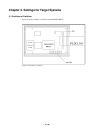
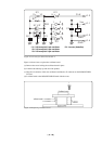
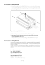
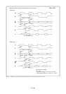
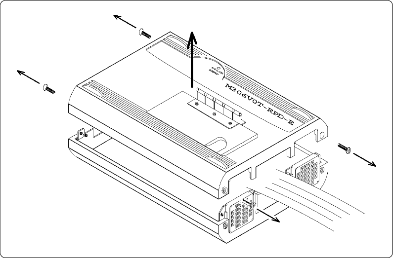
(1) You must remove the cover of the M306V0T-RPD-E in order to set the switches. To do so, remove
the four screws holding the top cover. There are two screws on each side (see Figure 4.12). Be
sure to turn OFF the power before attempting to change the switch settings. If the power is ON,
you may damage the circuits.
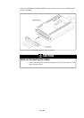
Figure 4.12 Removing M306V0T-RPD-E cover
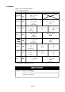
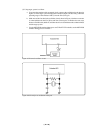
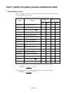
(2) After removing the cover, set the switches referring to Table 4.1 (page 19).
(3) After setting the switches, replace the cover by reversing the procedure for its removal.
1. Replace the M306V0T-RPD-E cover.
2. Replace the screws (two on each side) holding the M306V0T-RPD-E cover in place.
4.6 Procedure for Writing MCU File
You may need to change the contents of the MCU file, depending on the MCU being developed. The
MCU file is in the same directory as the emulator debugger. The file name is M30620.MCU for the
M16C/6V group MCUs.
The MCU file contains the following information: SFR area, internal RAM area, internal ROM area,
and firmware filename. Set these according to the MCU being developed. Use your editor to edit the
MCU file.
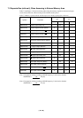
0 SFR area starting address
3FF SFR area ending address
2C00 Internal RAM starting address
3FFF Internal RAM ending address
F0000 Internal ROM starting address
FFFFFInternal ROM ending address
M30620B Firmware filename (Do not edit.)