


( 22 / 48 )
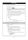
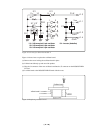
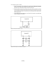
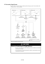
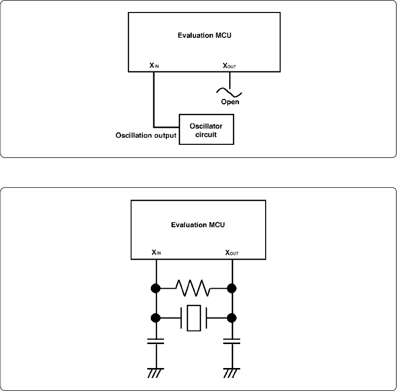
Figure 4.5 External oscillator circuit
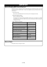
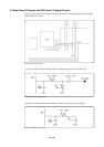
Figure 4.6 Circuit for no oscillation in this pod
(2) Using target system's oscillator
a. To operate the emulator with an external clock, construct the oscillation circuit shown in
Figure 4.5 in the target system and input the oscillation output at 40-60% duty (within the
operating range of the emulator's MCU) into the Xin (Xcin) pin.
b. Make note of the fact that in the oscillation circuit shown in Figure 4.6 where a resonator
is connected between the Xin (Xcin) and Xout (Xcout) pins, oscillation does not occur
because a flexible cable, buffer IC and other devices are used between the evaluation MCU
and the target system.
c. Use the M3T-PD30 emulator debugger to set CLK to EXT. For details, see the M3T-PD30
emulator debugger user's manual.