


( 11 / 78 )
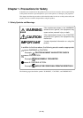
IMPORTANT
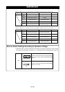
Note on DMA Transfer:
•With this product, the program is stopped with a loop program to a specific address. Therefore, if
a DMA request is generated by a timer or other source while the program is stopped, DMA transfer
is executed. However, make note of the fact that DMA transfer while the program is stopped may
not be performed correctly. Also note that the below registers have been changed to generate DMA
transfer as explained here even when the program is stopped.
DMA0 transfer counter register TCR0
DMA1 transfer counter register TCR1
Notes on Stack Area:
•With this product, a maximum 8 bytes of the user stack is consumed.
• If the user stack does not have enough area, do not use areas which cannot be used as stack (SFR
area, RAM area which stores data, or ROM area) as work area. Using areas like this is a cause of
user program crashes and destabilized emulator control. Therefore, ensure the +8 bytes maximum
capacity used by the user program as the user stack area.
Note on Address 0 Access:
• With the M16C/62 and 62A Group MCUs, when a maskable interrupt is generated, the interrupt
data (interrupt No. and interrupt request level) stored in address 0 is read out. Also, the interrupt
request bit is cleared when address 0 is read out. Consequently, when the address 0 readout
instruction is executed or when address 0 is read out in the cause of a program runaway, a
malfunction occurs in that the interrupt is not executed despite the interrupt request, because the
request bit of the highest priority interrupt factor enabled is cleared.
For this malfunction, when the reading out to the 0 address is generated excluding the interrupt, the
yellow LED lights up to alarm. When this LED lights, there is a possibility of wrong access,
therefore check the program. This LED is turned off by the RESET switch of the emulator main
unit.
Note on Stop and Wait Modes:
•Do not perform step execution at addresses in the stop or wait mode. It may cause communication
errors.
Note on Setting the Work Area:
• To use this product, it is necessary to set the work area in the internal reserved area of the MCU.
However, do not set it in the last 10 bytes of the internal reserved area. And be sure to set the internal
reserved area to INTERNAL. (Set the work area by INIT window of the emulator debugger M3T-
PD30.)
Example 1: When debugging the program of the MCU whose internal reserved area is 02C00
16
to
03FFF
16
address, set the work area within the range of 02C00
16
to 03FF6
16
address.
Example 2: When debugging the program of the MCU whose internal reserved area is 05400
16
to
05FFF
16
address, set the work area within the range of 05400
16
to 05FF6
16
address.
For instance, when setting the work area at 05C00
16
, the emulator uses 10 bytes area of 05C00
16
to
05C09
16
.