


( 21 / 78 )
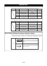
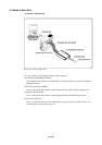
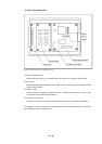
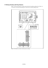
(2) Inside of Emulation Pod
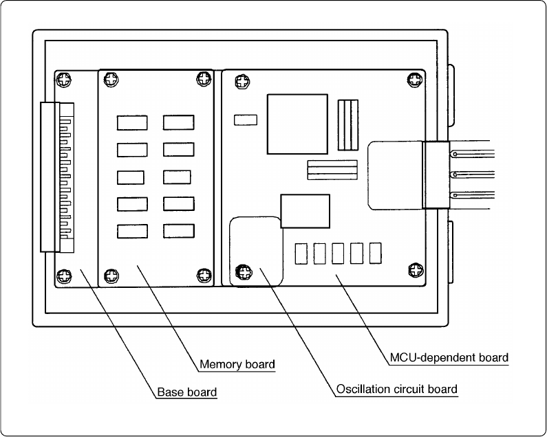
Figure 2.2 Internal view of emulation pod
(1) MCU-dependent board
Board which groups parts (pins and added functions) which vary according to MCU model.
(2) Base board
Board for the M16C/60 and M16C/20 Series MCUs which controls the interface with the PC4701
and the evaluation MCU.
(3) Memory board
Board on which is mounted the emulation memory (1 MB) and the map memory (4 bit × 1 M)
for the M16C/60 and M16C/20 Series MCUs.
(4) Oscillation circuit board
Oscillator circuit board on which the oscillation module device is mounted (16.000 MHz).
It is planned to enable customers to use future M16C/62 and 62A Group models by changing the
MCU-dependent board and MCU board.