


( 12 / 78 )
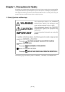
IMPORTANT
Notes on MAP References and Settings:
• For details on referencing and setting MAP information, see User's Manual of the emulator
debugger M3T-PD30.
• Be sure to set the SFR area to EXTERNAL (an external section).
•When setting 0FFFC
16
to 0FFFF
16
to EXTERNAL :
This product uses the 4 byte area 0FFFC
16
through 0FFFF
16
as the stack area. If this 4 byte memory
cannot be read or written to, reset cannot be properly effected. As a result, you need to alter the map
settings if the condition given below is met.
(1) With the system which shifts from the single-chip mode to the memory expansion (or
microprocessor) mode, using the 4 byte area of 0FFFC
16
to 0FFFF
16
set to EXTERNAL.
(2) With the system which starts up in microprocessor mode, using the 4 byte area of 0FFFC
16
to
0FFFF
16
set to EXTERNAL and there is not enough memory to read or write.
The procedures to alter the MAP settings when the conditions (1) or (2) above are met.
(1) Set the 4 byte area of 0FFFC
16
to 0FFFF
16
to INTERNAL.
(2) Execute the RESET command by use of the emulator debugger M3T-PD30.
(3) Set the stack pointer.
(Example)
RESET:
FCLR I
LDC #480H, SP <-- Set the stack pointer
(Stop the program after executing this instruction)
(4) Set the 4 byte area 0FFFC
16
through 0FFFF
16
to EXTERNAL.
Notes on Software Breaks and Hardware Breaks:
• Software breaks generate BRK interrupts by substituting the proper instruction to the BRK
instruction. Therefore, when referencing the result of a trace in bus mode, "00
16
" is displayed for
the instruction fetch address where a software break is set, and when referencing in reverse
assemble mode, "BRK" instruction is displayed.
• It is not possible to use a software break and a hardware break at the same time. If doing so, it may
not operate normally.
• In the area where the MAP setting is EXTERNAL, software breaks cannot be used.
Note on BRK Instruction:
• BRK instruction cannot be used.