


( 62 / 78 )
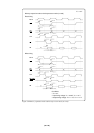
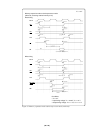
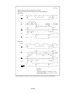
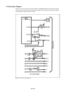
Figure 5.11 Connection diagram 1
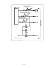
5.5 Connection Diagram
Figures 5.11 and 5.12 show the connection diagram of M30620T2-RPD-E. This connection diagram
mainly shows the interface section, and the circuits which are not connected to the target system such
as the emulator's control system are omitted.