


( 70 / 78 )
(2) Errors Occur When the Emulator Debugger Starts Up
(When the target system is connected)
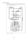
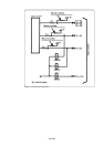
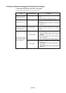
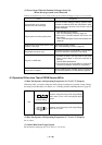
Table 6.2 Checkpoints of errors when starting up the emulator debugger (target is connected)
Error Checkpoint
Check all emulator debugger settings, interface cable
connection and switches on the rear of the PC4701 match.
See the instruction manuals of the PC4701 and the
emulator debugger.
(1) Download the proper firmware.
See "4.2 Downloading Firmware" (page 40).
(2) Recheck the connection between the PC4701 and
this product.
See "3.4 Connecting the PC4701 and Emulation
Pod" (page 33).
Download the proper firmware.
See "4.2 Downloading Firmware" (page 40).
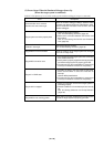
Check the reset pin of the target system has changed
from "Low" to "High" level.
(1) If the reset circuit of the target system has a watchdog
timer, disable the timer.
(2) Check power is properly supplied to the target system
and that the target system is properly grounded.
(3) The program may be uncontrollable in areas where
memory not allocated. Recheck the map setting.
(1) The MCU is either in the stop mode or wait mode.
Either reset the MCU or cancel the mode with an
interrupt.
See the MCU specifications.
(2) The program may be uncontrollable in areas where
memory not allocated. Recheck the map setting.
(1) Check the oscillation circuit of the target system is
oscillating properly.
(2) Check the switches in the emulation pod are correctly
set.
See "3.2 Setting Switches and Pullup Resistor"
(page 25).
Check power is properly supplied to the target system
and that the target system is properly grounded.
Communication error occurred
Data was not sent to the target
Target system cannot be properly built
PD30 version is not the same version as the
firmware in the target
Target MCU is in the reset state
Target MCU cannot be reset
Target is in HOLD state
Target clock is stopped
Target MCU is not receiving power