


Functional Overview
2.3.3 SDRAM
Rev.1.04
2008.7.10
2-5
REJ10J1564-0104
2
2.3.3 SDRAM
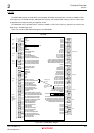
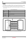
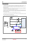
The M3A-HS85 can mount 16Mbytes of SDRAM (Not mounted). In the M3A-HS85 specification, 3.3V power is
supplied to SDRAM so that SH7285 should be used in 3.3V when SDRAM is mounted (CPU power supply switch
jumper (JP1) should be set to
“2-3”). The SDRAM is controlled by the bus state controller built into SH7285.
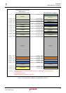
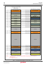
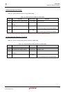
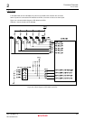
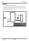
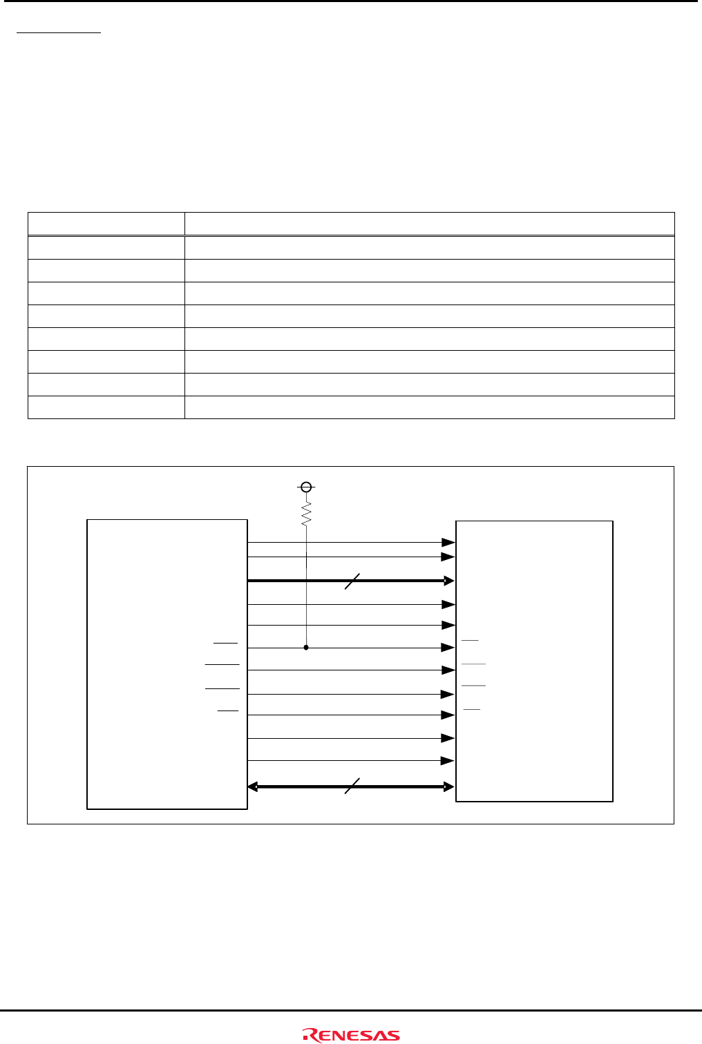
Table 2.3.2 lists the SDRAM specifications. Figure 2.3.2 shows the block diagram for the connection between
SH7285 and SDRAM.
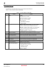
Table 2.3.2 SDRAM Specifications
Specification Content
Configuration 2M words x 16 bits x 4 banks (1pc.)
Capacity 16 Mbytes
Access Time 5.4ns
CAS Latency 2 (at 40MHz bus clock)
Refresh Interval 4096 refresh cycle every 64ms
Low Address A11- A0
Column Address A8 - A0
Number of Banks 4-bank operation controlled by BA0 and BA1
SH7285
PB12/CS3
PA12/DQMLU
PA13/DQMLL
PA15/CK
PA9/CKE
PA8/RDWR
PA6/RASL
PA7/CASL
PC14/A14
PC13/A13
BA1
BA0
DQMU
CLK
DQML
CS#
RAS#
CKE
WE#
CAS
A11-A0
SDRAM
(8M Word x 16bit)
BA1
BA0
DQ15-DQ0
DQMU
CLK
DQML
CS
RAS
CKE
WE
CAS
A11-A0
PC12/A12-PC1/A1
PD15/D15-PD0/D0
11
16
Figure 2.3.2 Block Diagram for the Connection Between SH7285 and SDRAM