Operational Specifications
3.1.5 DC Power Jack (J7)
Rev.1.04
2008.7.10
3-8
REJ10J1564-0104
3
3.1.5 DC Power Jack (J7)
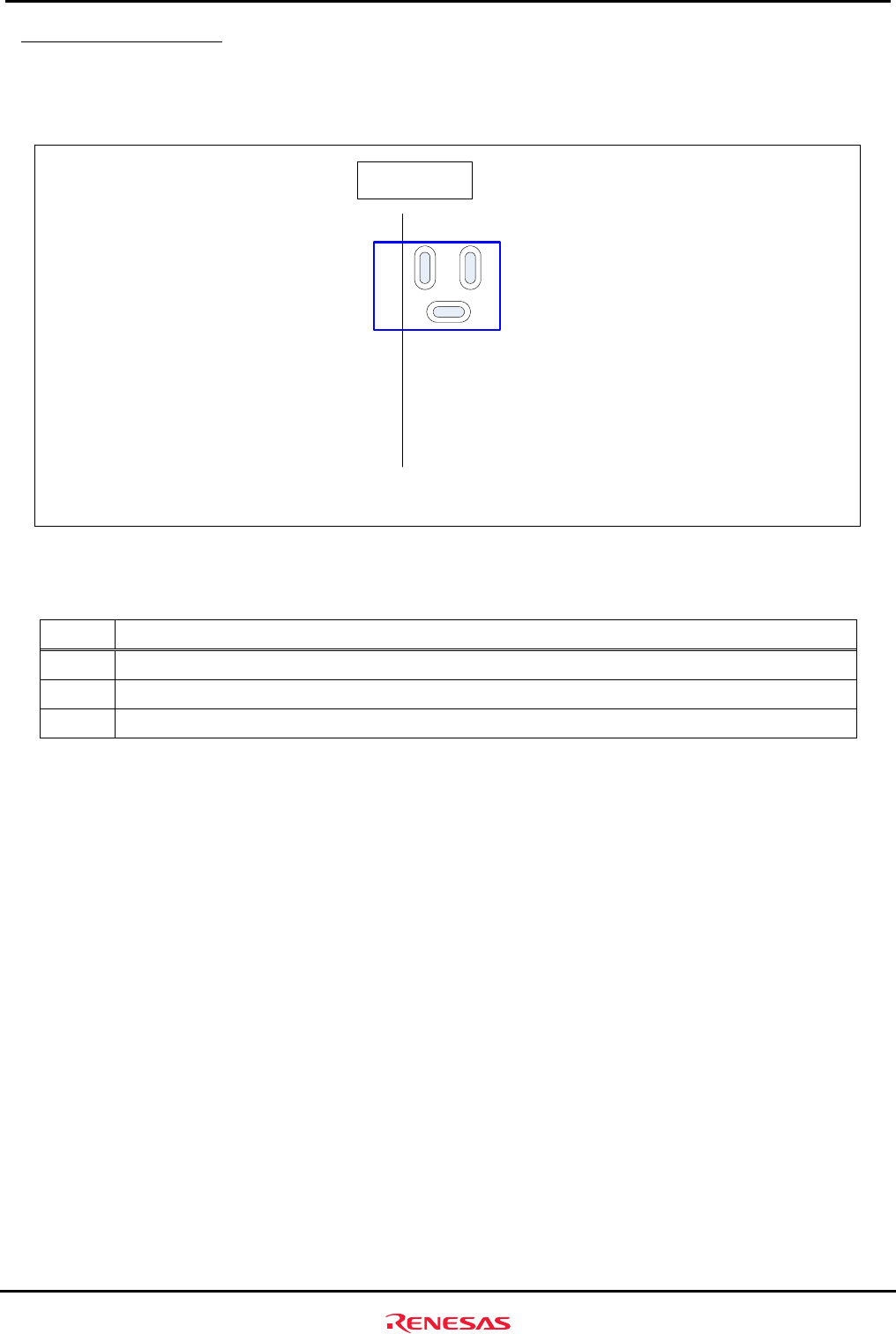
A DC power jack can be mounted on the M3A-HS85. Figure 3.1.7 shows the pin assignments of DC power jack,
and Table 3.1.7 lists the pin assignments of DC power jack (J7).
Board
edge
Top view of the
solder side
3
1
2
J7
Figure 3.1.7 Pin Assignments of DC Power Jack (J7)
Table 3.1.7 Pin Assignments of DC Power Jack (J7)
Pin Signal Name
1
+5V
2
GND
3
GND


