


Table of Contents
Chapter1 Overview..............................................................................................................................1-1
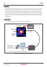
1.1 Overview .................................................................................................................................................................... 1-2
1.2 Configuration.............................................................................................................................................................. 1-2
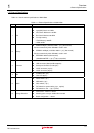
1.3 External Specifications ............................................................................................................................................... 1-3
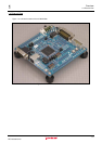
1.4 External View ............................................................................................................................................................. 1-4
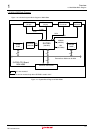
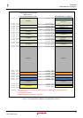
1.5 M3A-HS85 Block Diagram.......................................................................................................................................... 1-5
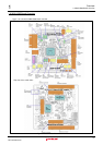
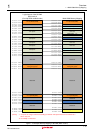
1.6 M3A-HS85 Board Overview ....................................................................................................................................... 1-6
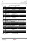
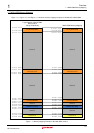
1.7 M3A-HS85 Memory Mapping ..................................................................................................................................... 1-8
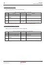
1.8 Absolute Maximum Ratings...................................................................................................................................... 1-11
1.9 Recommended Operating Conditions ...................................................................................................................... 1-11
Chapter2 Functional Overview ............................................................................................................2-1
2.1 Functional Overview................................................................................................................................................... 2-2
2.2 CPU............................................................................................................................................................................ 2-3
2.3 Memory ...................................................................................................................................................................... 2-4
2.3.1 SH7285 On-Chip Memory................................................................................................................................. 2-4
2.3.2 SRAM................................................................................................................................................................ 2-4
2.3.3 SDRAM ............................................................................................................................................................. 2-5
2.3.4 EEPROM........................................................................................................................................................... 2-6
2.4 Serial Port Interface.................................................................................................................................................... 2-7
2.5 I/O Ports ..................................................................................................................................................................... 2-8
2.6 Power Supply Module............................................................................................................................................... 2-11
2.7 USB Interface........................................................................................................................................................... 2-12
2.8 Clock Module............................................................................................................................................................ 2-13
2.9 Reset Module ........................................................................................................................................................... 2-14
2.10 Interrupt Switches................................................................................................................................................... 2-14
2.11 E10A-USB Interface ............................................................................................................................................... 2-15
Chapter3 Operational Specifications ...................................................................................................3-1
3.1 M3A-HS85 Connectors Outline .................................................................................................................................. 3-2
3.1.1 H-UDI Connector (J1, J2).................................................................................................................................. 3-3
3.1.2 Serial Port Connector (J3)................................................................................................................................. 3-5
3.1.3 Power Supply Connector (J4) ........................................................................................................................... 3-6
3.1.4 External Power Supply Connector for SH7285 (J5, J6)..................................................................................... 3-7
3.1.5 DC Power Jack (J7) .......................................................................................................................................... 3-8
3.1.6 Extension Connectors (J8-J12)......................................................................................................................... 3-9
3.1.7 Extension Connector (J13).............................................................................................................................. 3-15
3.1.8 USB Connector (J14) ...................................................................................................................................... 3-16
3.1.9 GND Connector (J15) ..................................................................................................................................... 3-17
3.2 Outline of Switches and LEDs.................................................................................................................................. 3-18
3.2.1 CPU Power Supply Select Jumpers (JP1) ...................................................................................................... 3-19
3.2.2 External Power Supply Select Jumper (JP2, JP3, JP4, JP5) .......................................................................... 3-20
3.2.3 FWE Pin Select Jumper (JP6)......................................................................................................................... 3-21
Rev. 1.04 2008.07.15 (i)
REJ10J1564-0104