


Functional Overview
2.6 Power Supply Module
Rev.1.04
2008.7.10
2-11
REJ10J1564-0104
2
2.6 Power Supply Module
In M3A-HS85, 5V power is input to the board and 3.3V is generated by using a regulator. The regulator used is
output voltage variable type and given voltage value can be generated by changing the resistance value.
5V power can be supplied from DC stabilized power supply (via power supply connector (J4)) and AC adapter (via
DC power supply jack (J7)).
SH7285 system power supply (VCC) can be switched to 3.3V/5V by setting 3V/5V select jumper (JP1)(Initially it is
set to 5V). When VCC is switched, please note the points shown as follows.
• When 5V is set in the state that SRAM or SDRAM is mounted, the voltage that exceeds the maximum rating is
supplied from the address line, data line, and control line to SDRAM or SRAM, and devices could be destroyed. Thus,
using like this must be avoided.
(3.3V is supplied to 3V system device such as SRAM and SDRAM even when 5V is set.)
By setting jumpers, system power (VSS), A/D power (AVCC), AVREF power, and USB power (DrVCC) of SH7285
can be individually supplied from external power supply.
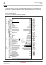
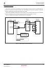
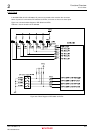
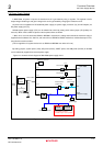
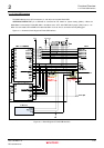
Figure 2.6.1 shows the block diagram of M3A-HS85 power supply circuit.
J4
Power
connector
Extension connector
Power switch
External
power supply
5VCC
5VCC
3VCC
5V
3.3V
VCC_CPU
VCC
AVCC
SH7285
SRAM
5VCC
DrVCC
(USB power supply)
AVREF
J8 connector
Extension connector
5VCC
AVCC
AVREF
J8 connector
JP4
JP5
JP3
External
power supply
JP2
3.3V/5V select
jumper (JP1)
J7
DC power jack
DC5V
input
SDRAM
3
1
2
VCC
It is not initially mounted.
Mountable only for 3.3V operation
Figure 2.6.1 Block Diagram of Power Supply Circuit