


Functional Overview
2.11 E10A-USB Interface
Rev.1.04
2008.7.10
2-15
REJ10J1564-0104
2
2.11 E10A-USB Interface
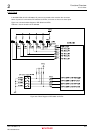
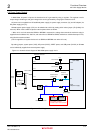
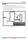
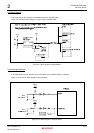
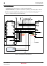
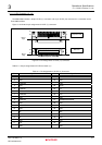
The M3A-HS85 has the H-UDI connectors (J1 and J2) to connect with E10A-USB.
ASEBRKAK
____________________
/ASEBRK
________________
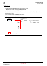
/FWE pin of SH7285 is connected to DIP switch for system setting (SW4-1). When the
M3A-HS85 is connected to E10A-USB, SW4-1 should be set to
“OFF” after FWE switch jumper (JP6) is set to “1-2”.
When it is connected to E10A-USB in the state that SW4-1 is set to
“ON”, it cannot be normally debugged.
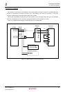
Figure 2.11.1 shows the block diagram of E10A-USB interface.
Figure 2.11.1 Block Diagram of E10A-USB Interface