


Operational Specifications
3.2.5 Switch and LED Functions
Rev.1.04
2008.7.10
3-23
REJ10J1564-0104
3
3.2.5 Switch and LED Functions
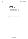
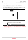
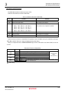
The M3A-HS85 includes six switches and seven LEDs.
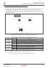
Table 3.2.5 lists switches mounted on M3A-HS85.
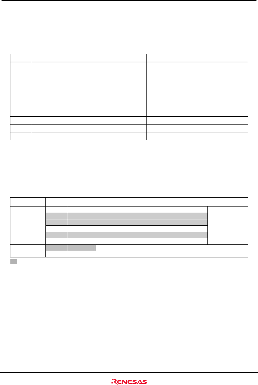
Table 3.2.5 Switches Mounted on M3A-HS85
No. Function Remarks
SW1 System power on/off switch -
SW2 System reset input switch See section 2.9 for details.
SW3 DIP switch for user (4-pole)
SW3-1 OFF : PE0=”H” ON : PE0=”L”
SW3-2 OFF : PE1=”H” ON : PE1=”L”
SW3-3 OFF : PE2=”H” ON : PE2=”L”
SW3-4 OFF : PE3=”H” ON : PE3=”L”
PE0, PE1, PE2, and PE3 are pulled up.
See section 2.5 on chapter 2 for details.
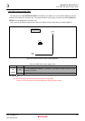
SW4 System setup DIP switch (4-pole) See Table 3.2.6 for the functions
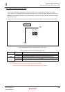
SW5 NMI input switch See section 2.10 for details.
SW6 IRQ1 input switch See section 2.10 for details.
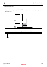
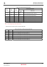
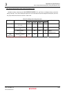
Table 3.2.6 lists the functions of switch SW4. The operation mode of SH7285 is set by the combination of the pins
FWE, MD0, and MD1. Table 3.2.7 lists the SH7285 operating mode setting.
FWE pin is multiplexed with the
ASEBRK
_______________
/ASEBRKAK
___________________
signal. When E10A-USB is used, SW4-1(FWE) must be set
to
“OFF”.
Table 3.2.6 Functions of Switch SW4
No. Setting Function
OFF FWE="H" (Releasing the writing/erasing protects of on-chip flash memory) SW4-1
FWE
ON FWE="L" (Setting the writing erasing protects of on-chip flash memory)
OFF MD1 pin state "H" SW4-2
MD1
ON MD1 pin state "L"
OFF MD0 pin state "H" SW4-3
MD0
ON MD0 pin state "L"
Operating mode
setting
(See Table 3.2.7)
OFF H1=”H” SW4-4
TP
ON H1=”L”
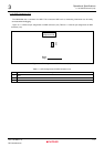
It is connected to a test hole (H1). You can use it freely like connecting it to the
input pin of SH7285 via H1.
: Initial Setting