


Operational Specifications
3.1.1 H-UDI Connector (J1, J2)
Rev.1.04
2008.7.10
3-3
REJ10J1564-0104
3
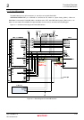
3.1.1 H-UDI Connector (J1, J2)
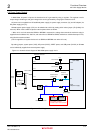
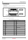
The M3A-HS85 includes a 36-pin H-UDI (J1) connector and 14-pin H-UDI (J2) connector for a connection to the
E10A-USB emulator.
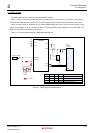
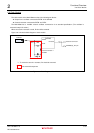
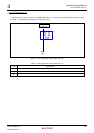
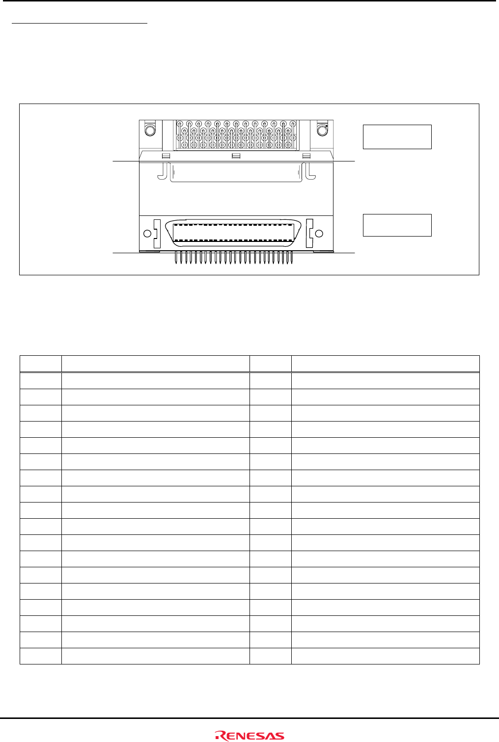
Figure 3.1.2 shows the pin assignments of H-UDI (J1) connector.
1
2
35
36
Board
edge
Board
edge
Top view of the
component side
Side view
1
2
35
36
Figure 3.1.2 Pin Assignments of H-UDI (J1) Connector
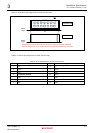
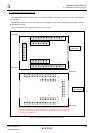
Table 3.1.1 lists pin assignments of H-UDI connector (J1).
Table 3.1.1 Pin Assignments of H-UDI (J1) Connector
Pin Signal Name Pin Signal Name
1
AUDCK
19
TMS
2
GND
20
GND
3
AUDATA0
21
TRST
_________
4
GND
22
(GND)
5
AUDATA1
23
TDI
6
GND
24
GND
7
AUDATA2
25
TDO
8
GND
26
GND
9
AUDATA3
27
ASEBRKAK
___________________
/ASEBRK
______________
10
GND
28
GND
11
AUDSYNC
________________
29
UVCC
12
GND
30
GND
13
NC
31
RES
_______
14
GND
32
GND
15
NC
33
GND
16
GND
34
GND
17
TCK
35
NC
18
GND
36
GND