


Operational Specifications
3.1.6 Extension Connectors (J8-J12)
Rev.1.04
2008.7.10
3-9
REJ10J1564-0104
3
3.1.6 Extension Connectors (J8-J12)
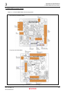
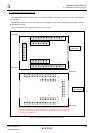
The M3A-HS85 includes the through-hole for mounting extension connectors to which the I/O pins of the SH7285
are connected.
MIL standard connectors can be connected to J8-J12, allowing users to connect with extension boards or monitor
the SH7285 bus signals.
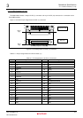
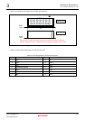
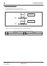
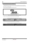
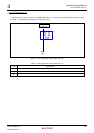
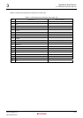
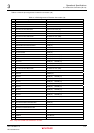
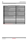
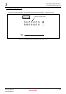
Figure 3.1.8 shows the pin assignments of extension connector.
Board edge
19 20
12
J10
40
39
2
1
20
19
2
1
Top view of the
solder side
J12
J11
40
39
2
1
20
19
2
1
J9
J8
Board edge
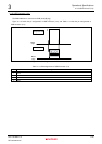
1920
12
J10
40
39
2
1
20
19
2
1
J12
J11
40
39
2
1
20
19
2
1
J9
J8
Top view of the
component side
Board edge
Board edge
[Note] The pin numbers on CPU board are defined based on the assumption that extension
connectors are installed in the component side. Thus, the assignments of pin number on the
extension connector side and the CPU board side are different when extension connectors
are installed in the solder side.
Figure 3.1.8 Pin Assignments of Extension Connectors