


Operational Specifications
3.2.6 Jumper Switch Setting when Using Development Tool
Rev.1.04
2008.7.10
3-25
REJ10J1564-0104
3
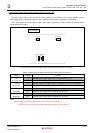
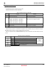
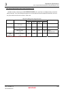
3.2.6 Jumper Switch Setting when Using Development Tool
SH7285
’s emulator related signals (FWE/ASEBRKAK
_____________________
/ASEBRK
________________
, TDI, and TDO) are multiplexed with on-chip flash
writing control pin. Thus, when development tools such as E10A-USB and Flash Development Toolkit (FDT) are used,
the jumper switch should be set as shown in Table 3.2.9.
Table 3.2.9 Setting when Using Connectors
Setting
Tool Connector
JP6 JP7,8 SW4-1 SW4-2,3
Remarks
E10A-USB H-UDI connector
(J1 or J2)
“1-2” “1-2” OFF -
Serial port connector
(J3)
- “2-3” OFF
*1
- FDT
USB connector
(J14)
- “2-3” OFF
*1
OFF
OFF
Mode 7
USB boot mode
Flash
programmer
Extension connector
(J13)
“2-3” “1-2” - -
Note:*1: When JP6 is set to “1-2”, it must be set to “OFF”.