


Operational Specifications
3.2.4 Serial Port Select Jumper (JP7, JP8)
Rev.1.04
2008.7.10
3-22
REJ10J1564-0104
3
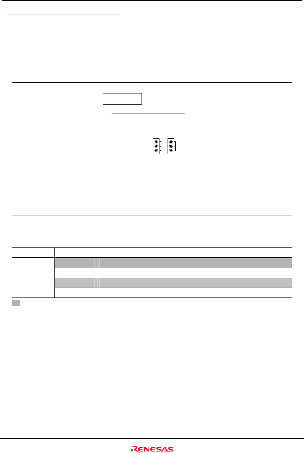
3.2.4 Serial Port Select Jumper (JP7, JP8)
SCI channel of SH7285 connecting to the serial port connector (J3) is changed by the setting of JP7 and JP8.
SCIF channel 3 is connected to the serial port connector (J3) as the initial setting. When SCI channel 0 is
connected to the serial port connector (J3), note that H-UDI connectors (J1 and J2) and the extension connector
(J13) cannot be used.
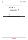
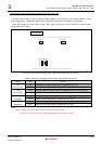
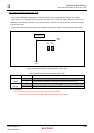
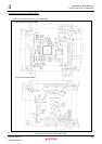
Figure 3.2.5 shows the serial port select jumper assignments. Table 3.2.4 lists the serial port select jumper setting.
Top view of the
component side
Board
edge
Board
edge
1
3
JP7
TXD
SEL
TXD0
TXD3
1
3
JP8
RXD
SEL
RXD0
RXD3
Figure 3.2.5 Serial Port Select Jumper Assignments (JP7, JP8)
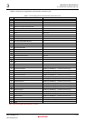
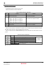
Table 3.2.4 Serial Port Select Jumper Setting (JP7, JP8)
Jumper Setting Function
1-2
Pin PE5/TXD3 of SH7285 is connected to the serial port connector (J3).
JP7
TXDSEL
2-3 Pin PA1/TXD0 of SH7285 is connected to
the
serial port connector (J3).
1-2 Pin PE4/RXD3 of SH7285 is connected to
the
serial port connector (J3). JP8
RXD SEL
2-3 Pin PA0/RXD0 of SH7285 is connected to
the
serial port connector (J3).
: Initial Setting
Note: Do not change jumper settings during the operation of M3A-HS85.
Ensure to turn off the power for the M3A-HS85 before changing jumper settings.