R5C841 PCI-CardBus/IEEE 1394/SD Card/Memory Stick/xD/ExpressCard Data Sheet
12345 2004 REV. 1.10 3-13
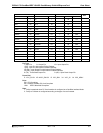
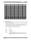
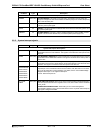
Pin Name Type Description
PCI Bus Interface Pin Descriptions (Continued)
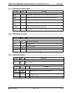
SERR# OUT (OD) SYSTEM ERROR: This signal is pure open drain. The R5C841 actively drives this
output for a single PCI clock when it detects an address parity error on either the primary
bus or the secondary bus.
REQ# OUT (TS) REQUEST: This signal indicates to the arbiter that the R5C841 desires use of the bus.
This is a point to point signal.
GNT# IN GRANT: This signal indicates the R5C841that access to the bus has been granted. This
is a point to point signal.
GBRST# IN GLOBAL RESET: This input is used to initialize registers for control of PME_Context
register. This should be asserted only once when system power supply is on.
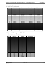
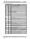
3.3.2 System Interrupt signals
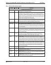
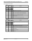
Pin Name Type Description
System Interrupt Pin Descriptions
INTA# OUT (OD)
PCI INTERRUPT REQUEST A: This signal indicates a programmable interrupt request
generated from the PC Card interface. This signal is connected to the interrupt line of the
PCI bus.
INTB# OUT (OD)
PCI INTERRUPT REQUEST B: This signal indicates a programmable interrupt request
generated from the IEEE 1394 interface. This signal is connected to the interrupt line of
the PCI bus.
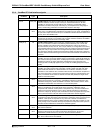
INTC# OUT (OD)
PCI INTERRUPT REQUEST C: This signal indicates a programmable interrupt request
generated from the Memory Stick interface, the SD Card interface or the xD Picture Card
interface. This signal is connected to the interrupt line of the PCI bus.
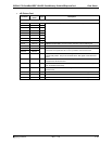
UDIO0/SRIRQ#
UDIO1/GPIO0
UDIO2/GPIO1
UDIO3/GPIO2
UDIO4/GPIO3
UDIO5/LED0#
I/O (TS)
USER DEFINABLE INPUT/OUTPUT: These signals can be used as user-definable
input/output. Users can define functions such as *GPIO, LED, IRQ and so on for each
pin in the PC Card Misc Control 4 Register. For details, refer to “PCI-CardBus Bridge
Registers Descripion” in the registers description.
*GPIO : General Purpose I/O
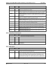
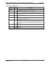
RI_OUT#/
PME#
OUT (OD)
RING INDICATE OUTPUT: When 16-bit card is inserted and Ring Indicate Enable bit in
the Interrupt and General Control register is set to one, RI# on the IO Card is forwarded
to RI_OUT#.
POWER MANAGEMENT EVENT: When PME_En bit in Power Management
Control/Status register is set or when Power Status is set to any state mode except D0,
this signal is assigned as PME#.


