R5C841 PCI-CardBus/IEEE 1394/SD Card/Memory Stick/xD/ExpressCard Data Sheet
12345 2004 REV. 1.10 3-17
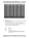
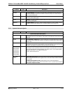
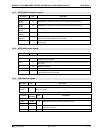
3.3.7 IEEE1394 PHY Interface signals
Pin Name Type Description
IEEE1394 Cable Interface Pin Descriptions
TPAP1
TPAP0
I/O
TPA Positive : Twisted-pair cable A (positive) differential signal terminals.
TPBP1
TPBP0
I/O
TPB Positive : Twisted-pair cable B (positive) differential signal terminals.
TPAN1
TPAN0
I/O
TPA Negative : Twisted-pair cable A (negative) differential signal terminals.
TPBN1
TPBN0
I/O
TPB Negative : Twisted-pair cable B (negative) differential signal terminals.
TPBIAS1
TPBIAS0
I/O
TP Bias : Twisted-pair bias output. This pin is compliant with the IEEE1394a-2000, and
also monitors Insertion/desertion of other cables
CPS IN
Cable Power Status : This pin detects the Cable Power Status. See in Spec.4.22.3 for
details of CPS.
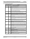
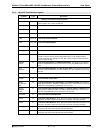
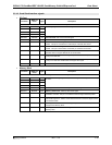
3.3.8 IEEE1394 Control signals
Pin Name Type Description
IEEE1394 Control Pin Descriptions
VREF I/O
Voltage reference Resistance : It is necessary to connect a capacitance of 0.01uF
between this pin and AGND.
REXT I/O
Resistance External: It is necessary to connect a resistor of 10kΩ±1% between this pin
and AGND.
XI IN
X’tal In : 24.576MHz
XO OUT
X’tal Out : 24.576MHz
FIL0 I/O
Filter : This pin connects to the PLL Filter. It is necessary to connect a capacitance of
0.01uF between this pin and AGND.
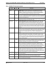
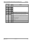
3.3.9 USB Interface signals
Pin Name Type Description
USB Interface Pin Descriptions
USBDP
USBDM
I/O
USB Data Port: These signals are differential signals. These signals are connected to HOST
USB D+/D- signals.
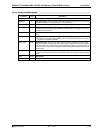
Pin Name
PC Card
Pin Name
Type Description
USB Interface Pin Descriptions
USBD+ IORD#
USBD- IOWR#
I/O
USB Data Port: These signals are differential signals.
CPUSB# CADR22 IN
USB ExpressCard Detect: This signal indicates whether the USB ExpressCard
is inserted to a socket.
PERST# CDATA2 OUT
ExpressCard Reset : This signal is a reset signal to ExpressCard.


