R5C841 PCI-CardBus/IEEE 1394/SD Card/Memory Stick/xD/ExpressCard Data Sheet
12345 2004 REV.1.10 4-12
PHY function
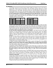
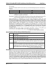
On D2 and D3 states, the PHY can be set to any one of the following low power consumption by
Software.
Doze Mode Sleep Mode
Select Condition All of Ports status is set to Disconnected, Disabled or Suspended.
Resume Time less than 200ns less than 10ms
Doze Mode: Stopping clock of the PHY digital block and getting the Cable Interface’s power down
enables the low power consumption.
Sleep Mode: In addition to the low power consumption by Doze mode, getting power down of PLL
and the oscillator enables the lower power consumption than on Doze mode.
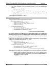
Setting D2PhyPM bit or D3PhyPM bit on the PHY Power Management register (the 1394
OHCI-LINK Configuration register addr.98h) enables a selection of Doze mode or Sleep mode.
On Doze mode or Sleep mode, LinkOn event enables to resume from the power saving mode
automatically and PME# is asserted. Each power saving modes cannot be set without the above
selected conditions, even if the R5C841 is set to D2 state or D3 state. If the above Ports
conditions are not satisfied, the R5C841 transacts as the Repeater PHY. In this time, setting
D2ForcePM bit or D3ForcePM bit to 1b enables to ignore above conditions and to set Doze mode
or Sleep mode automatically. But, it is disabled LinkOn event to resume from the power
consumption mode automatically and to assert PME#. Writing into Power State bits enables to
return to D0 state.
In addition, don’t the power supply of VCC_RIN, VCC_ROUT*, VCC_3V, VCC_MD3V and
AVCC_PHY3V on the suspend mode in spite of the Software and the Hardware.
(*: in case of an internal regulator disabled)
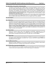
4.11.3 Function on SD Card / Memory Stick/xD Picture Card
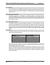
D0 The maximum powered state. All PCI/SD Card/Memory Stick/xD Picture Card transactions
are acceptable.
D1 Only the PCI Configuration Space access is allowed while the power and clock are
provided. SDCCLK and MSCCLK are output.
D2 Only the PCI Configuration Space access is allowed while the power and clock are
provided. SDCCLK and MSCCLK are output.
D3hot Only the PCI Configuration Space access is allowed while the power and clock are
provided. SDCCLK and MSCCLK are stopped compulsorily. When the function is brought
back to the D0 state, the reset is automatically performed regardless of the assertion of
PCIRST#.
D3cold PCI-CardBus Bridge defines D3cold state is to change from VCC_RIN, VCC_ROUT*,
VCC_3V and VCC_MD3V to the auxiliary power source. The R5C841 supports power
management events from D3cold with the auxiliary power source. The R5C841 can
generate PME# even in D3cold state without PCI clock if the event source is SD Card
Detect Change or Memory Stick Detect Change or xD Picture Card Detect Change.
(*: in case of an internal regulator disabled)
4.12 GPIO
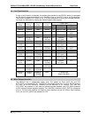
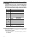
UDIO1, 2, 3 and 4 pins work as GPIO (General Purpose I/O) pin when GPIO Enable bit of the PC
Card Misc Control 4 register (A4h bit31) is set to “1” on Serialized IRQ (default) mode or on
UDIO_Select mode of the PC Card Misc Control 4 register. When GPIO Enable bit is set to “0”,
GPIO outputs are Hi-Z and GPIO Inputs are disabled. User can change the characteristics of the
GPIO pins to either Input or Output by setting either I/O control bits on the GPIO register (83Ah)
or the General Purpose I/O 1 register of the Config register space (AAh). When GPIO Enable bit
is set to “1”, setting of GPIO is input mode (default). And it is possible to read the states of their
pins through each bit of the GPIO register. On Output mode, the written states of each bit are
output. If GPIO functions are not used on Serialized IRQ mode, no pull-up is required.


