


Spinpoint M8U-Internal Product Manual REV 3.4
48
INSTALLATION
6.3.2 Common USB Packet Fields
Field formats for the token, data, and handshake packets are described in the following section. Packet bit
definitions are displayed in unencoded data format. The effects of NRZI coding and bit stuffing have been
removed for the sake of clarity. All packets have distinct Start- and End-of-Packet delimiters.
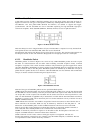
Sync
All packets must start with a sync field. The sync field is 8 bits long, which is used to synchronise the clock
of the receiver with the transmitter. The last two bits indicate where the PID fields starts.
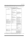
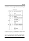
PID
PID stands for Packet ID. This field is used to identify the type of packet that is being sent. The
following table shows the possible values.
ADDR
The address field specifies which device the packet is designated for. Being 7 bits in length allows for 127
devices to be supported. Address 0 is not valid, as any device which is not yet assigned an
address must respond to packets sent to address zero.
ENDP
The endpoint field is made up of 4 bits, allowing 16 possible endpoints. Low speed devices, however can
only have 2 endpoint additional addresses on top of the default pipe. (4 Endpoints Max)
CRC
Cyclic Redundancy Checks are performed on the data within the packet payload. All token packets
have a 5 bit CRC while data packets have a 16 bit CRC.
EOP
End of packet. Signalled by a Single Ended Zero (SE0) for approximately 2 bit times followed by a J for 1 bit
time.
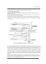
6.3.2.1 SYNC Fields
All packets begin with a synchronization (SYNC) field, which is a coded sequence that generates a
maximum edge transition density. It is used by the input circuitry to align incoming data with the local
clock. A SYNC from an initial transmitter is defined to be eight bits in length for full/low-speed and 32 bits
for high-speed. Received SYNC fields may be shorter. SYNC serves only as a synchronization mechanism
and is not shown in the following packet diagrams. The last two bits in the SYNC field are a marker that is
used to identify the end of the SYNC field and, by inference, the start of the PID.
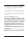
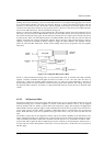
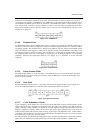
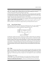
6.3.2.2 Packet Identifier Fields
A packet identifier (PID) immediately follows the SYNC field of every USB packet. A PID consists of a
four-bit packet type field followed by a four-bit check field as shown in Figure 6-14. The PID indicates the
type of packet and, by inference, the format of the packet and the type of error detection applied to the
packet. The four-bit check field of the PID ensures reliable decoding of the PID so that the remainder of the
packet is interpreted correctly. The PID check field is generated by performing a one’s complement of the
packet type field. A PID error exists if the four PID check bits are
not complements of their respective
packet identifier bits.
Figure 6-14: PID Format