


Spinpoint M8U-Internal Product Manual REV 3.4
50
INSTALLATION
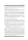
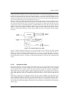
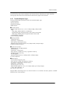
The function address (ADDR) field specifies the function, via its address, that is either the source or
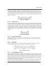
destination of a data packet, depending on the value of the token PID. As shown in Figure 6-15, a total of
128 addresses are specified as ADDR<6:0>. The ADDR field is specified for IN, SETUP, and OUT tokens
and the PING and SPLIT special token. By definition, each ADDR value defines a single function. Upon
reset and power-up, a function’s address defaults to a value of zero and must be programmed by the host
during the enumeration process. Function address zero is reserved as the default address and may not be
assigned to any other use.
Figure 6-15: ADDR Field
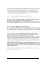
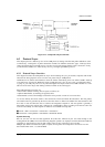
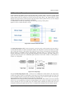
6.3.2.4 Endpoint Fields
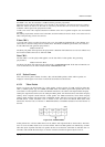
An additional four-bit endpoint (ENDP) field, shown in Figure 6-16, permits more flexible addressing of
functions in which more than one endpoint is required. Except for endpoint address zero, endpoint numbers
are function-specific. The endpoint field is defined for IN, SETUP, and OUT tokens and the PING special
token. All functions must support a control pipe at endpoint number zero (the Default Control Pipe). Low
speed devices support a maximum of three pipes per function: a control pipe at endpoint number zero plus
two additional pipes (either two control pipes, a control pipe and an interrupt endpo
int, or two interrupt
endpoints). Full-speed and high-speed functions may support up to a maximum of 16 IN and OUT
endpoints.
Figure 6-16: Endpoint Field
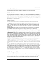
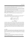
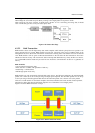
6.3.2.5 Frame Number Fields
The frame number field is an 11-bit field that is incremented by the host on a per-frame basis. The frame
number field rolls over upon reaching its maximum value of 7FFH and is sent only in SOF tokens at the
start of each (micro) frame.
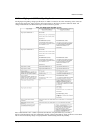
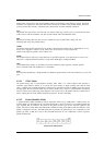
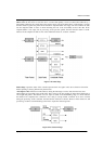
6.3.2.6 Data Fields
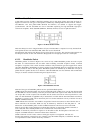
The data field may range from zero to 1,024 bytes and must be an integral number of bytes. Figure 6-17
shows the format for multiple bytes. Data bits within each byte are shifted out LSb first.
Figure 6-17: Data Field Format
6.3.2.7 Cyclic Redundancy Checks
Cyclic redundancy checks (CRCs) are used to protect all non-PID fields in token and data packets. In this
context, these fields are considered to be protected fields. The PID is not included in the CRC check of a
packet containing a CRC. All CRCs are generated over their respective fields in the transmitter before bit
stuffing is performed. Similarly, CRCs are decoded in the receiver after stuffed bits have been removed.
Token and data packet CRCs provide 100% coverage for all single- and double-bit errors. A failed CRC is
considered to indicate that one or more of the protected fields is corrupted and causes the receiver to ignore
those fiel
ds and, in most cases, the entire packet.
For CRC generation and checking, the shift registers in the generator and checker are seeded with an allones
pattern. For each data bit sent or received, the high order bit of the current remainder is XORed with