INTERFACE SPECIFICATIONS
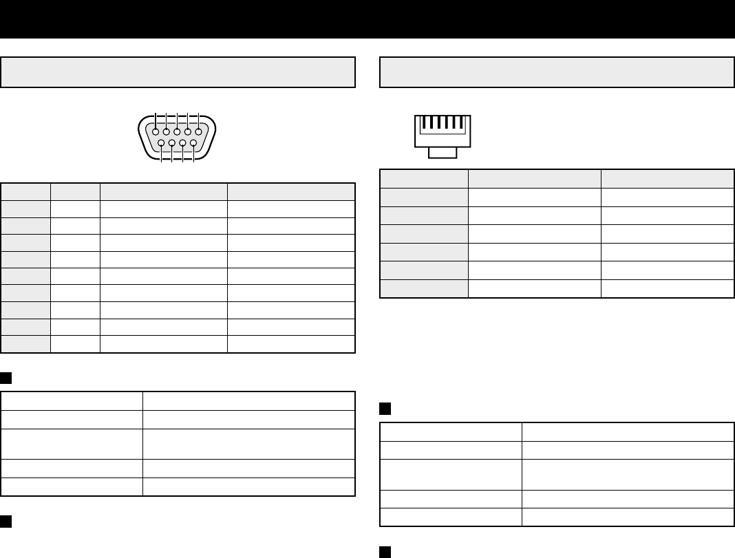
RS232C (9-pin connector layout)
Pin No. Signal Function Signal direction
1 –– –
2 RXD Data reception Computer → Multiplexer
3 TXD Data transmission Multiplexer → Computer
4 –– –
5 GND Ground –
6 –– –
7 RTS Request to send Multiplexer → Computer
8 –– –
9 –– –
DATA FORMAT
Mode Asynchronous
Character length 8 bits
Data transmission speed 2400, 4800, 9600, 19200 bps
(set in the (SERIAL SET) menu)
Parity check None
Stop bit One bit
TRANSMISSION PROTOCOL
The transmission is based on 1 byte units. After the computer
has transmitted 1 byte, it will wait for an answer from this unit,
then send the following byte of data.
The command ON (F6) is sent to start, and the command OFF
(F7) is sent to finish. This unit will receive the commands, and
will reply to each command by ACK (0A). (Refer to “COMMAND
TABLE 4” on page 52.)
RS-485 (RJ-11 connector layout)
Pin No. A terminal signal B terminal signal
1 Not used Not used
2 Not used Not used
3 A signal B signal
4 B signal A signal
5 Not used Not used
6 Not used Not used
A: Non-inverting driver output/receiver input
B: Inverting driver output/receiver input
Transmission line: 2 conductors
Transmission system: Half duplex
DATA FORMAT
Mode Asynchronous
Character length 8 bits
Data transmission speed 2400, 4800, 9600, 19200 bps
(set in the (SERIAL SET) menu)
Parity check None
Stop bit One bit
TRANSMISSION PROTOCOL
A proprietary protocol (SSP: Security Serial Protocol) is used.
Operates using a Sanyo controller or a controller using
containing this protocol.
9876
54321
123456
L8FC5/US (MPX-CD162, MD162 GB) 2000. 8. 31
48 English


