


Unit 6: Maintenance
LM408-412e Operator Manual
6-3 PN: 9001155A
REPLACEMENT PROCEDURES
This chapter provides in-depth instruction on all primary component and assembly replacement, in addition to most
secondary components. Use the text in conjunction with their accompanied graphics to ensure complete
comprehension throughout the process. Especially observe all cautionary or warning notations.
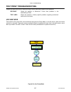
PRINT HEAD REPLACEMENT
If the print head becomes damaged or worn, it can be easily removed and replaced without having to make critical
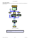
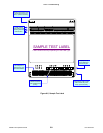
adjustments. Before replacing the print head, check the head counter values by printing a test pattern. Instructions
relating to the Head Counter may be found in the Configuration unit of this manual.
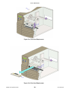
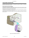
1. Switch off the printer, disconnect power supply cord, and remove media/ribbon.
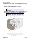
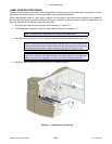
2. Open the right housing cover and latch print head release lever (1, Figure 6-1a) as necessary.
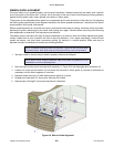
3. Remove screw (2) from upper print assembly (3) securing defective print head (4, Figure 6-1b).
4. Unlatch print head release lever (1) and withdraw defective print head (4) from within print assembly (3).
5. Disconnect the two wiring harnesses (not shown) from defective print head (4).
6. Reconnect two wiring harnesses (not shown) to replacement print head (4).
7. Insert replacement print head (4) into print assembly (3) and latch lever (1, Figure 6-1a).
8. Secure replacement print head (4) to print assembly (3) and secure using screw (2).
9. Restore power, reset the head counter, and test print.
CAUTION: STATIC ELECTRICITY CAN RESULT IN COMPONENT DAMAGE.
OBSERVE APPROPRIATE GROUNDING PROCEDURES WHEN REPLACING ANY
COMPONENTS.
NOTE: Each of the printer’s wiring harness connectors are different from all others to
ensure proper mating. Mate each matching half for reconnection.
CAUTION: EXCERCIZE CARE WHEN INSTALLING THE PRINT HEAD TO
ENSURE THAT ITS ELEMENTS ARE NOT DAMAGED DURING INSTALLATION.
NOTE: Apply the print to the upper surface fo the print assembly’s print bracket and
ensure the alignment pins insert into their respective slots.