


Unit 4: Printer Configuration
S8400 Series Operator Manual
4-26 PN: 9001160B
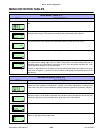
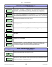
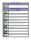
Determines whether the print data code requires deletion. Hexadecimal graphic data will not be
deleted. Select YES to delete all Carriage Returns (CR) and Line Feed (LF) commands in the
data stream - including graphics and 2D bar codes. Select the NO option to process them.
This feature is primarily used to maintain compatibility with earlier models of SATO printers.
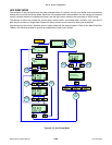
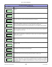
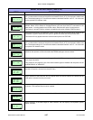
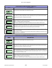
Allows the selection of which interface board will be set up in subsequent menus. Interface Port 1
(I/F-1) is the smaller card slot of the printer and Interface Port 2 (I/F-2) is the printer’s middle card
slot. The default setting is I/F-2 and accommodates a standard interface card. I/F-1 is to be used
for the optional PCI interface cards.
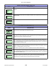
Allows setting of bi-directional communication protocol.
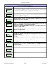
Allows the selection of the receive buffer type. Select MULTI for multiple-item buffer and 1ITEM
for a single item buffer.
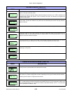
Allows setting for ACK width of the IEEE1284 interface. The display will appear when the
interface is present and one item (1ITEM) is selected as a receive buffer.
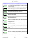
Allows item number check to be enabled or disabled. Will only appear when STATUS5 is set for
the protocol.
Allows BCC Check for ACK width of the IEEE1284 interface. The display will only appear when
STATUS5 is set for the protocol.
Allows the determination of whether the Cancel (CAN) and Data Link Escape (DLE) codes will be
processed or ignored. Select the YES option to ignore the codes and NO to process them.
This screen will only appear when the communication protocol is STATUS4.
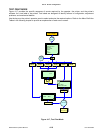
SERIAL INTERFACE MODE (TABLE 4-4)
MENU DESCRIPTION
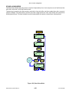
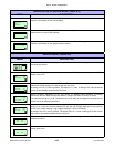
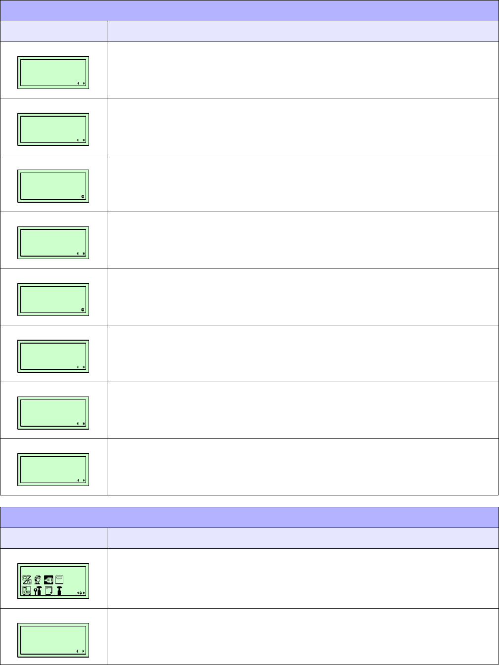
Is the premiere screen of the Interface Mode. The Interface Mode allows the parameters to be set
for the printer to communicate with a host and vice-versa.
Select the YES option to configure an interface board for bi-directional communication, the menu
will advance to multiple configuration screens depending on the type of interface board installed.
Selecting the NO option will bypass those screens.
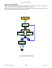
PARALLEL INTERFACE MODE (TABLE 4-3)
MENU DESCRIPTION
IGNORE CR/LF
YES NO
INTERFACE BOARD
SETTING
I / F – 1 I / F - 2
PROTOCOL
STATUS4
STATUS5
RECEIVE BUFFER
MULTI 1 ITEM
IEEE1284
ACK SIGNAL
XX.X US
ITEM NO. CHECK
ENABLE DISABLE
BCC CHECK
ENABLE DISABLE
IGNORE CAN/DLE
YES NO
INTERFACE MODE
INTERFACE BOARD
SETTING
YES NO