


112
Wiring the Motor Power Connector (Drive end)
Wiring the Motor
Power Connector
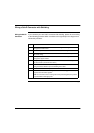
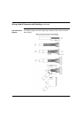
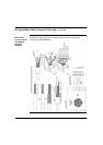
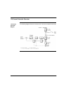
If you construct your own motor power connector, please do so according to the
following procedure which correlates to the 13 steps in the diagram that follows this
procedure.
Continued on next page
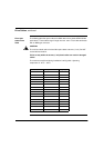
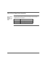
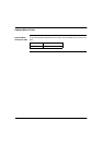
Step Action
1 Carefully remove about 70 mm of the outer jacket while taking care not to
damage the braided shield.
2 Push the grommet over the cable until the end is flush with the jacket.
3 Push the outer braided shield back over the grommet.
4 Position the shielding for the brake wires over the outer shielding braid and
ensure good electrical contact.
5 Push the filling wires and protective cloth back over the shielding.
6 Push the shrink tubing (30mm long) over the shielding and leave about 15mm
exposed.
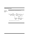
7 Use a hot-air blower to shrink the tubing then shorten the wires for U, V, W to
45mm and those for BR+, BR- to 55mm.
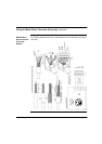
8 Carefully remove about 10mm of the ends of the wires while taking care not to
damage the copper strands.
9 Attach crimp ferrules to the ends of the wires
10 Place the shielding plate in the connector housing and push the contact tabs
into the PE terminal clamp of the connector.
11 Attach the cable with the strain relief.
12 Ensure the clamping loop of the strain relief sits properly on the shielding braid.
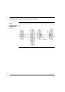
13 Push the wire ferrules into the corresponding terminals in the connector and
tighten.