


45
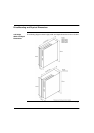
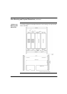
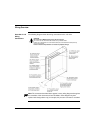
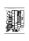
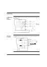
Connection diagram for Lexium 17S
Reference Safety Instructions
and Use As Directed!
Sine-Cosine
Encoder
Resolver
M
thermal control
included
15
thermal control
included
8
6
5
4
3
Resolver
V
W
P
U2
V2
W
PE
B+
B-
2
1
high
resolution
single /
multiturn
Regeneration
resistor
F
B1
FB2
PE-connection (protective earth)
earth connection (panel)
shield connection via plug
COM1/COM2
PC
X6
X5
X3
X1
X2
X9
U
Brake-
Brake+
Analog 1 in -
Analog Com
Analog 2 in +
Analog 2 in -
Reserved
I/O Com
Input 3
Analog 1 in +
Input 4
Input 1
Input 2
Enable
Output 1
Output 2
Fault RA
Fault RB
ROD
SSI
Ma./SI.
3
encoder-
evaluation,
slave/master
amplifier
Safety
circuit
Digital2
Digital1
+24V referenced
to 0V/GND
I/O-GND
GND
+ +/-10V speed
setpoint2
referenced to GND
GND
GND
+ +/-10V speed
setpoint1
referenced to GND
4
5
1
6
7
8
10
9
18
13
14
11
12
15
16
17
2
3
Analog Com
Reserved
X8
2
1
Remove jumper if external
regen resistor is connected
3
4
+RBint
-RB
n.c.
+R
Bext
PE
L1
L2
L3
X0A
1
2
3
4
FN
FN
FN
Master
contactor
PEL1 L2 L3
supply unit
24V DC
1
2
3
4
+24 Vdc
X4
24 Vdc Com
FH
1234 1234
DC+ DC+DC- DC-
X7
X0B
L1 L2 L3 PE
shielding if cable
is longer than 20cm
shield connection at the front panel
to other amplifiers