


Installation 19
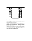
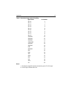
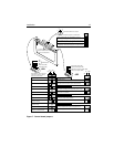
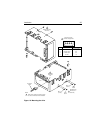
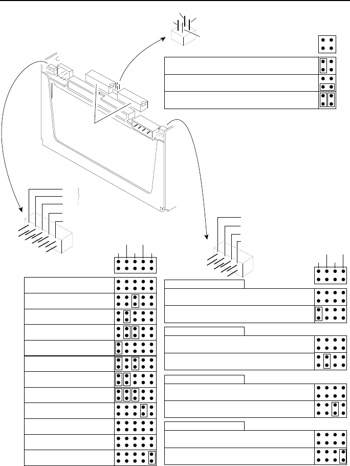
SCSI Selectors
J4A
ID2
ID1
ID0
Write Protect (WP)
Master/Slave (MS)
Spinup Delay option (SD)
Start Command option (SC)
SCSI Bus Parity Check option (PAR)
Sweep Cycle option (SWP)
J4B
Terminator Resistor-Paks
(must be installed if drive is at
either end of daisychain)
1
2
3
4
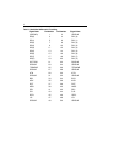
Terminator Power Source Jumper
Assign the terminal power jumpers as shown below.
Initiator supplies power over the SCSI bus source for
terminators. Drive supplies no terminator power.
Drive supplies power for its own terminator resistor-paks but
not to the SCSI bus (factory setting).
Drive supplies power for the external terminator at the end of
the daisychain. Terminator resistor-paks must be removed.
4
2
3
1
Spinup Delay option (SD)
Immediate spinup
(if the Start Command option jumper is disconnected)
Spinup delay equal to the SCSI bus ID multiplied by 10 seconds
(if the Start Command option jumper is disconnected)
SD PAR
SC SWP
Start Command option (SC)
Start spindle according to the Spinup Delay option jumper
Spindle spinup is delayed until a Start Unit command is
received from the SCSI bus
SCSI bus parity check (PAR)
Enable parity check of SCSI bus data
Ignore parity
Sweep Cycle option (SWP)
Disable sweep cycles (recommendation — sweep cycles
should be enabled at the system or subsystem level)
Enable sweep cycles at the drive level
Select SCSI ID, write protect, and
master/slave options by placing
jumpers as shown below.
ID2 ID0
ID1 WP
MS
SCSI ID = 0
SCSI ID = 1
SCSI ID = 2
SCSI ID = 3
SCSI ID = 4
SCSI ID = 5
SCSI ID = 6
SCSI ID = 7
Write Protect = On
(prevents writing)
Write Protect = Off
(enables writing)
Master drive for spindle sync
Slave drive unless selected as the
master by a SCSI command
Recommended only for the last drive on the daisychain.
*
*
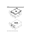
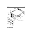
Figure 7. Control board jumpers