


Installation 27
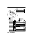
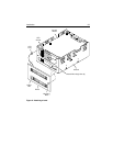
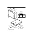
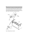
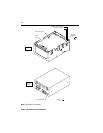
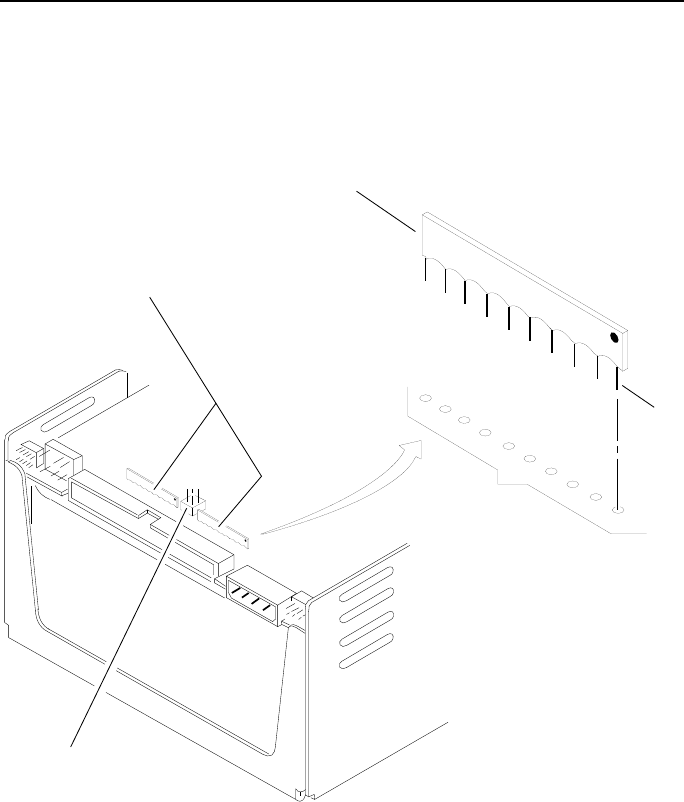
Figure 12 shows how the terminator resistor-paks are attached on drives with
single-ended I/O. The terminator resistor-paks, which are single inline pack-
ages, mount in the rows of holes located in the control board. Ensure that they
are installed with the correct orientation (indicated by a dot above pin 1) to
terminate these drives.
Terminator
Resistor-Pak
(note orientation)
Terminator
Resistor-Paks
(single inline
packages)
Mounting Holes
in Control Board
Terminator Power
Source Jumper
Pin
1
Figure 12. Terminator attachment—single-ended I/O