


34
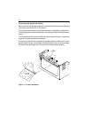
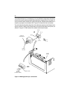
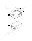
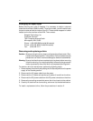
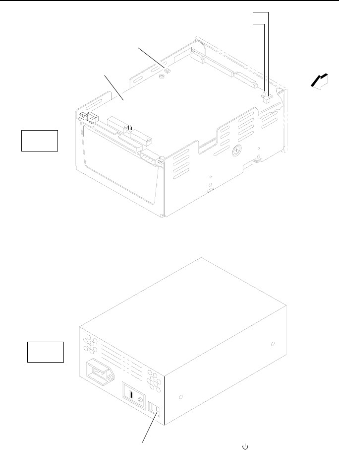
Note. Differential unit shown.
Figure 16: Switches and indicators
On / Standby Switch
Socket for Active LED (red)
Heartbeat LED (green)
Active LED
(on optional
bezel)
Ready LED (green)
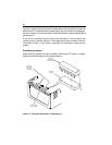
Control
Board
Drive
Power
Supply
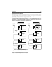
Standby =
On = I