


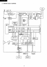

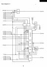
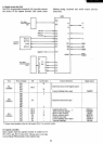
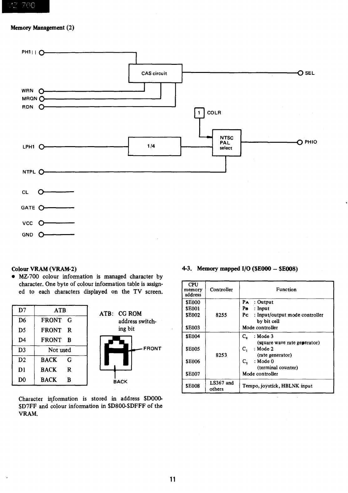
Memory Management
(2)
PH111
WRN
MRQN
RDN
LPH1
NTPL
CL
GATE
VCC
GND
0
0
0
0
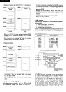
Colour VRAM (VRAM-2)
CAS
circuit
1/4
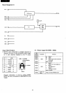
•
MZ-
700 colour infonnation
is
managed character by
character. One byte
of
colour infonnation table is assign-
ed
to
each characters displayed on the
TV
screen.
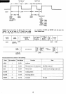
D7
D6
D5
D4
D3
D2
D1
DO
ATB
FRONT G
FRONT R
FRONT
B
Not used
BACK
G
BACK R
BACK
B
ATB: CGROM
address switch-
ingbit
....
+-_FRONT
BACK
Character iqfonnation
is
stored in address
$DOOQ.
$D7FF and colour infonnation in $D80Q.$DFFF
of
the
VRAM.
11
~------------------------------<1SEL
COLR
NTSC
PAL
select
~-------------In
PH
10
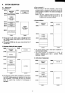
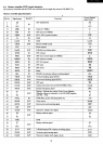
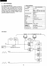
4-3. Memory
mapped
I/O
($EOOO
-
$EOO8)
CPU
memory Controller
Function
address
$EOOO
PA
: Output
$EOOl
Pe : Input
$E002
8255
Pc
: Input/output mode controller
by bit cell
$E003 Mode controller
$E004
Co
: Mode 3
(square wave rate ge»erator)
$E005
C,
: Mode 2
8253
(rate generator)
$E006
C
2
: Mode 0
(terminal counter)
$E007
Mode controller
$E008
LS367 and
Tempo,joystick,
HBLNK input
others