


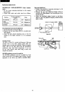
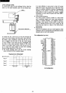
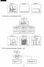
2) Pen exchange method
To remove pen, press the pen exchange button, when the
slider
is
at the right handside, push the pen release lever.
Motor
Push
the
pen release lever
To install the pen, push the tip
of
the pen through the
ring
of
the return spring in the nrst place, then push into
the holder. Upon completion, ensure
that
the tip
of
the
pen
is
engaged with the hole
of
the pen return spring.
If
colour change
is
done when the pen
is
disengaged from
the hole, it may cause improper rotation
of
the rotary
holder
as
the slider makes contact with the pen. Do
not
try to rotate the rotary holder
by
hand when installing
the pen during replacement
of
the pens.
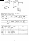
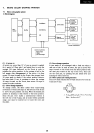
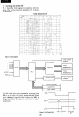
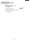
• The X-axis stepping motor and the Y-axis stepping
motor are driven
by
the two-phase magnet.
Stepping
motor
driving signal
Basic
drive pulse
n
n n
t---
Phase
A
Phase
B
Phase
C
Phase
0
Motor
clock
Hold
period
~
tMH
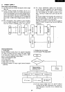
21
It
is
more effective to
save
power
to
shut
off
current
while the X and
Y axis motors are
at
a halt. But, there
may be a possible malfuction because
of
unsuppressed
vibration,
if
the current
is
turned
off
with a normal
pulse width.
In
order
to
prevent this, current
is
applied
excessively for more than the given hold time (tMH
=
1 ms
or
more).
• Colour position detector
The colour position detector consists
of
a reed switch
and a permanent magnet and
it
may cause malfunction
owing
to
external vibration, and magnetic influence.
Especially, when deposit
of
alien matter
or
paper
frag-
ments is between the left end
of
the carriage and the
frame this may result in a failure
of
the colour detect
performance.
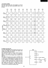
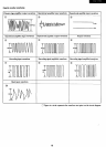
• Character set
Input
of
an undefmed code
up
to
$20
is
ignored. Other
undefmed codes are represented in hexadecimal notation
using the pen in a
next
color pOsition.
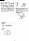
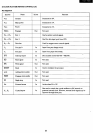
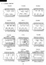
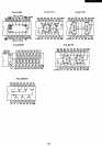
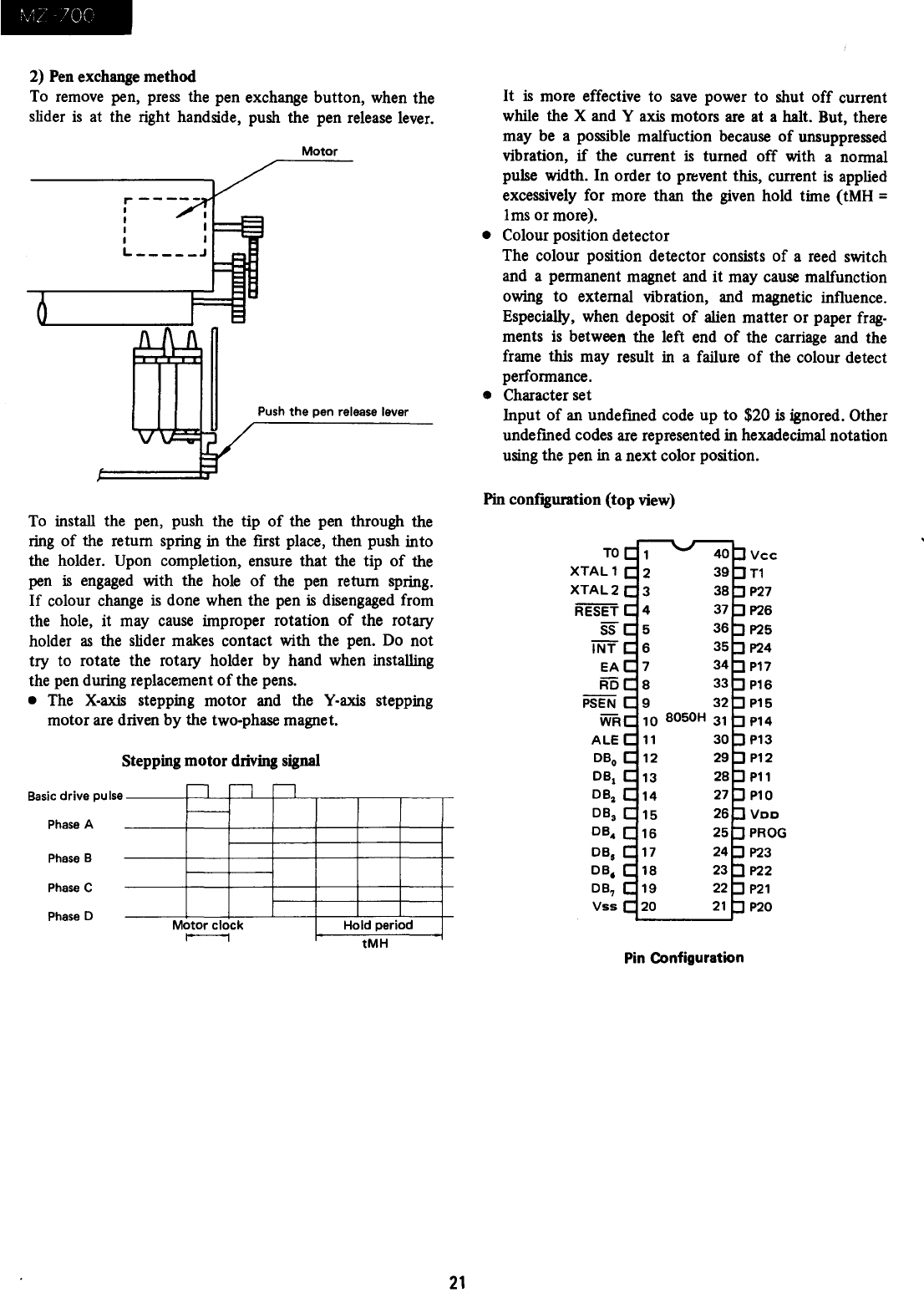
Pin configuration
(top
view)
TO
Vcc
XTAL1
T1
XTAL2
P27
RESET
P26
SS
P25
INT
P24
EA
P17
RD
P16
PSEN
P15
WR
P14
ALE
P13
DBo
P12
DBI
P11
DB2
P10
DB,
VDD
DB4
PROG
DBs
P23
DB,
P22
DB,
P21
Vss
P20
Pin Configuration