


~\;1Z
700
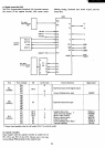
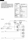
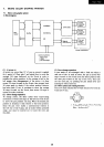
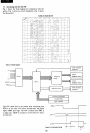
5-2.
External recorder playback circuit
When
the external recorder
is
used, connection
is
made
with the 8255
by
shorting P-12. In this condition, the
write data (8255
PC
output)
is
differentiated and sent
to the recorder.
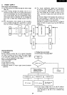
In
the case
of
read, the signal peak
is
chopped by
DI
and D2 (about
O.6V),
amplified in the
1.2V limiter (about 1.2V), then amplified
to
5V in the
next stage amplifier. The phase
of
the read signal may
be
inverted with the tape switch after this
is
to compensate
for phase difference owing to the head
of
the recorder.
When
proper operation
is
not attained with an external
recorder, adjust the volume control and the tone control
knobs to optimum positions. Those which incorporate
treble and base for tone control should preferably be set to
a flat condition, and those with only a tone control knob,
should be set to a high condition.
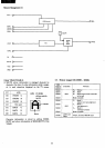
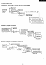
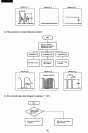
6.
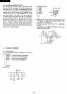
COLOUR ENCODER
6-1. Colour encoder
• The encoder unit should
be
replaced
as
a unit part.
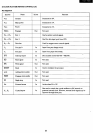
• Input signals
• COLOR
•
CSYNC
•
HSYNC
•
VSYNC
• R
• G
• B
Colour sub-carrier
wave
frequency
Composite synchronizing signal
Horizontal synchronizing signal
Vertical synchronizing signal
• CVIDEO
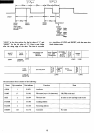
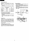
'X.
Rear
view
,~
B/W-Colour
sw
I + +
6+
? I
RF
CH1-
VIDEO
8pin
OUT
CH2
OUT
Din
SW
19
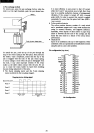
• 8-Pin DIN connector
I VIDEO
2 GND
'5'
VSYNC
4
HSYNC
'3'
CSYNC
6 R
7 G
8 B
7~~
3 •
S'
8 4
2
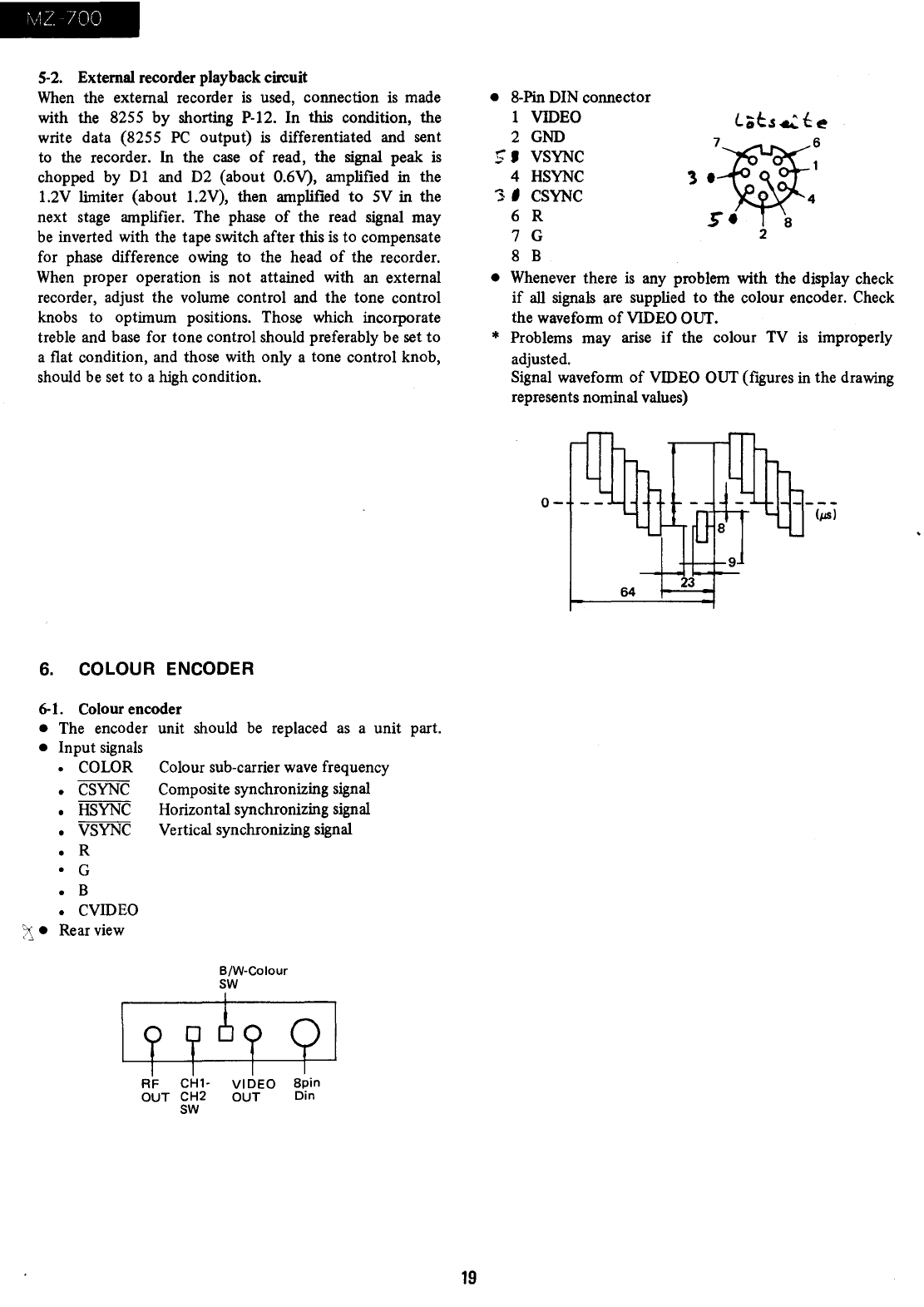
• Whenever there
is
any problem with the display check
if
all
signals are supplied to the colour encoder. Check
the waveform
of
VIDEO OUT.
* Problems may arise
if
the colour TV
is
improperly
adjusted.
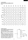
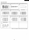
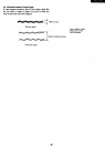
Signal waveform
of
VIDEO OUT (figures in the drawing
represents nominal values)
0-
--
64