


~1Z
-7CO
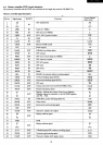
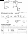
At the time
of
manual reset (with I
CTRL
I in depression)
$0000
$0000
SYSTEM
~
MONITOR
-
(ROM)
$1000
$1000
SYSTEM
$0000
$0000
V-RAM
V-RAM
$EOoo
KEY
and
TIMER
PORT
SYSTEM
$FOOO
~
MEMORY CHANGE
'--
Disable
Enable
•
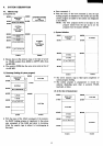
When
the I C T R L I key
is
in depression, address $0000
through $OFFF and
$DOOO
through $FFFF become
the
RAM
area.
• With input
of
the command ":If' when the monitor
(ROM)
is
active, it
is
switched
to
the
RAM.
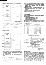
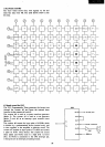
e) Floppy bootstrap
$0000
....--------,
MONITOR
(ROM)
$1000
f----------I
SYSTEM
iI-
Iv
$DOOO~----~
V-RAM
V-RAM
$EOoo
i-
K
-
E
-
y
-an-d T-IM-E-R-PO-R-l
-I
$FOoo
f----------I
FLOPPYCONTRO~L-
Enable
$0000 I
SYSTEM
$1000
~----~
LOAD
$0000
,------,
SYSTEM
Disable
• Because the floppy control area
is
mapped to
$FOOO
for
compatibility with the
MZ-80K series, boot begins
from the adress
$FOOO.
•
Map
configuration after boot will
be
considered sepa-
rately.
4-2. Memory controller
(CRT
C)
Both the momory controller and the CRT controller
are
contained in a
single
chip custom
LSI
(M60719), it
has the following functions:
5
a.
8 x 8 dot characters are displayed on the CRT screen
of
40
characters (horizontal) x 25 lines (vertical). Displayed
character font
is
dependent on the
4KB
character
generator (ROM).
b.
Manages
the monitor
ROM,
DRAM, video
RAM,
and
peripherals (keyboard, timer,
ETC.) mapped to the
memory.
c.
Generates clock to the Z-80A microprocessor.
d.
Selects the printer I/O port.
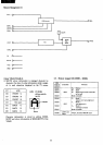
1)
CRT controller
There are major variations
of
colour television systems
as
described below.
1.
NTSC
system (Japan, U.S.A., etc.)
2.
PAL system (U.K., Germany, etc.)
3.
SECAM
system (French, etc.)
Because
of
the different specification requirements above,
the
MZ-
700 may not be suitable for overseas operation.
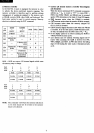
PAL signal specification
Signal name
Signal frequency
NTPL
"L"
LPHI 17.734475
MHz
CLKN
8.8672375
MHz
COLR
4.43361875
MHz
WAD
1.108404688
MHz
PHIO 3.546875
MHz
HBLN
15.6113
kHz
VBLN 50.0363
Hz
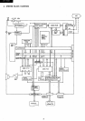
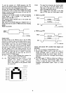
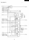
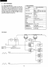
CRT
controller
system
block
diagram
H
NTPL
CPU
WA
CPU
Blanking period
COLR
HSY
SYN
VBLK
HBLK
CLK
LOAD
TV
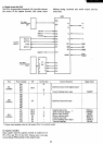
Oata written in
the
VAAM
from
the
CPU
is
input
to
01-08
via
the
bidirectional
buffer
5245.
To display characters on the CRT screen, the
CPU
writes
the character data ( display code) to the
2KB
VRAM-l
along with the control signal
WR
and the color data
of
that character
to
the
2KB
VRAM-
2.
In other words,
as
the address
($DOOO
,..,
$D7FF)
is
output. The character
data
is
supplied to the VRAM-l input (01-08)
via
the bidirectional buffer LS245, and the data will then
be written when
WE
is
low. The color data
is
also sent to
01-08
of
the
VRAM-2
to be written when
WE
is
low.