


,Q
700
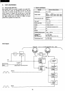
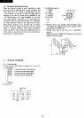
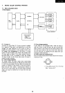
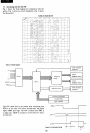
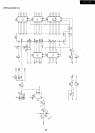
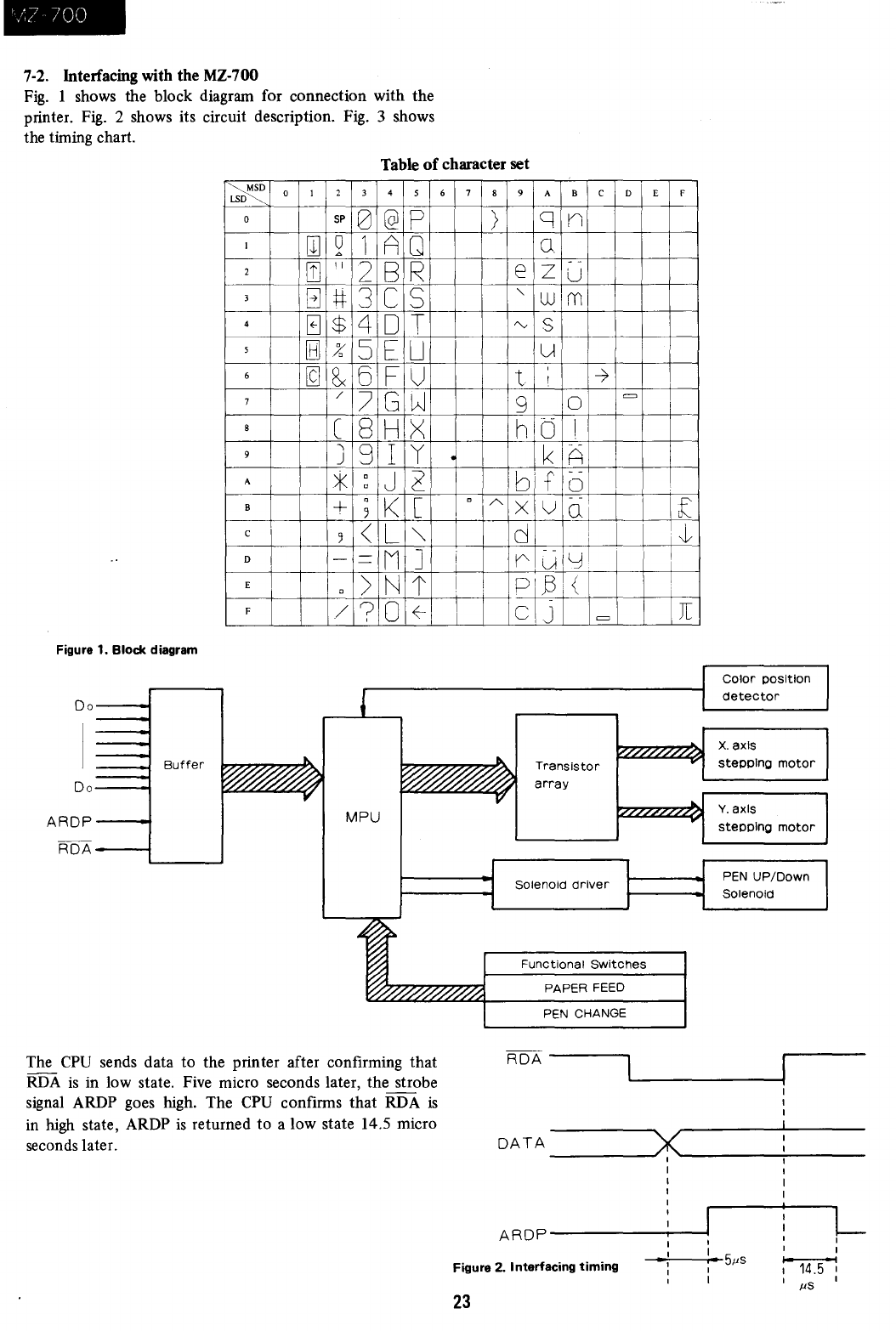
7-2. Interfacing with the MZ-700
Fig.
1 shows the block diagram for connection with the
printer.
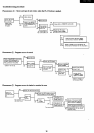
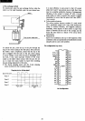
Fig.
2 shows its circuit description. Fig. 3 shows
the timing chart.
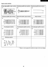
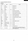
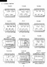
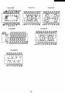
Table
of
character set
Figure 1. Block diagram
00---1
00---1
AROP---t
ROA---;
Buffer
~
LSD
0
I
2
3
4
5
6
7
8
9
A
B
c
D
E
F
0 I
W
[1]
B
0
[8J
[g
2 3 4
5
sp
0
@
p
0
1 A
Q
""
11
2
B
R
#
3
C
S
$
4
0 T
%
5
E
U
8x
6
F U
/
7 G
W
C
8
H
><
,
9 I
'I
j
*
c
J
~
c
+
c
K
[
5
5
<
L
""
-
-
M
]
-
c
>
N
t
/
?
0
~
MPU
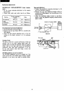
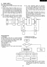
The
CPU
sends data to the printer after confirming that
RDA
is
in low state. Five micro seconds later, the strobe
signal ARDP goes high. The
CPU
confirms that RDA
is
in high state, ARDP
is
returned to a low state 14.5 micro
seconds later.
6
7
c
i
I
8
>
A
9 A B C
q
n
0
-
e
z
U
"
w
m
"v
S
u
t
,
---1
1
9
0
h 0
I
k
A
b' f
- -
0
- -
X
V
01
d
i
r
uiyl
PI,B i {
C J
=
TranSistor
array
Solenoid
driver
D
=
Functional
Switches
PAPER FEED
PEN CHANGE
ROA
-----,
E F
1
[
\~
\
[
Color
position
detector
X.axls
stepping
motor
Y.axls
stepping
motor
PEN
UP/Down
SOlenoid
DATA
______
~~~------~------
I
I
I
A
ROP
------r-----I,
L
1
I
-I
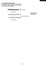
Figure 2. Interfacing
timing
-+---i-: --5,us
1
14.5 1
I
,
,us
23