


8.
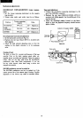
POWER SUPPLY
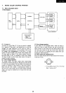
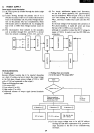
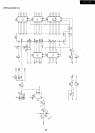
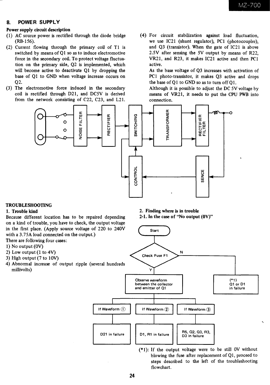
Power supply circuit description
(1)
AC
source power
is
rectified through the diode bridge
(RB-156).
(2) Current flowing through the primary coil
of
T1
is
switched by means
of
Q 1
so
as
to induce electromotive
force in the secondary coil. To protect voltage fluctua-
tion on the primary side,
Q2
is
implemented, which
will
become active to deactivate
Ql
by dropping the
base
of
Q1
to
GND
when voltage increase occurs on
Q2.
(3) The electromotive force induced
in
the secondary
coil
is
rectified through D21, and DC5V
is
derived
from the network consisting
of
C22, C23, and L21.
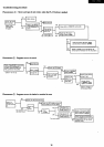
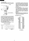
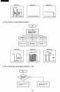
TROUBLESHOOTING
1.
Trouble kind
a:
w
I-
..J
u:::
w
en
(5
z
a:
!!!
u..
~
U
w
a:
Because different location has to
be
repaired depending
on a kind
of
trouble, you have to check, the output voltage
in the first place. (Apply source voltage
of
220 to 240V
with a 3.75A load connected
on
the output.)
There are following four cases:
1)
No output
(OV)
2) Low output
(1
to 4V)
3)
High
output (7 to 10V)
4) Abnormal increase
of
output ripple (several hundreds
millivolts)
021
in
failure
(!)
~
J:
U
I-
~
en
..J
o
a:
I-
z
o
U
MZ-700
(4) For circuit stabilization against load fluctuation,
we
use
IC21
(shunt regulator),
PC1
(photocoupler),
and
Q3
(transistor).
When
the gate
of
IC21
is
above
2.5V after sensing the
5V
output by means
of
R22,
VR21, and R23, it makes
IC21
active and then
PC1
active.
As
the
base
voltage
of
Q3
increases with activation
of
PC1
photo-transistor,
it
makes
Q3
active
and drops
the base
ofQ1
to
GND
so
as
to turn offQ1.
Although it
is
possible to adjust the
DC
5V
voltage by
means
of
VR21, it needs to
put
the
CPU
PWB
into
connection.
a:
w
~
a:
0
u..
en
Z
~
a:
I-
a:
W
u..a:
-w
1-1-
U..J
w_
a:u..
w
U
Z
w
en
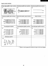
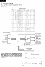
2. Finding where
is
in
trouble
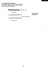
2-1. In the case
of
"No output
(OV)"
N
Observe waveform
between
the
collector
and
emitter
of
01
(*1 )
01
or
01
in
failure
24
01,
R1
in
failure
R5,
02, 03,
R3,
03
in
failure
(*1):
If
the output voltage
were
to
be
still
OV
without
blowing the fuse after replacement
of
Q1,
proceed to
steps described to the left
of
the troubleshooting
flowchart.
,