


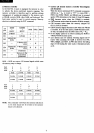

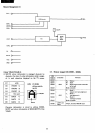
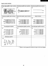
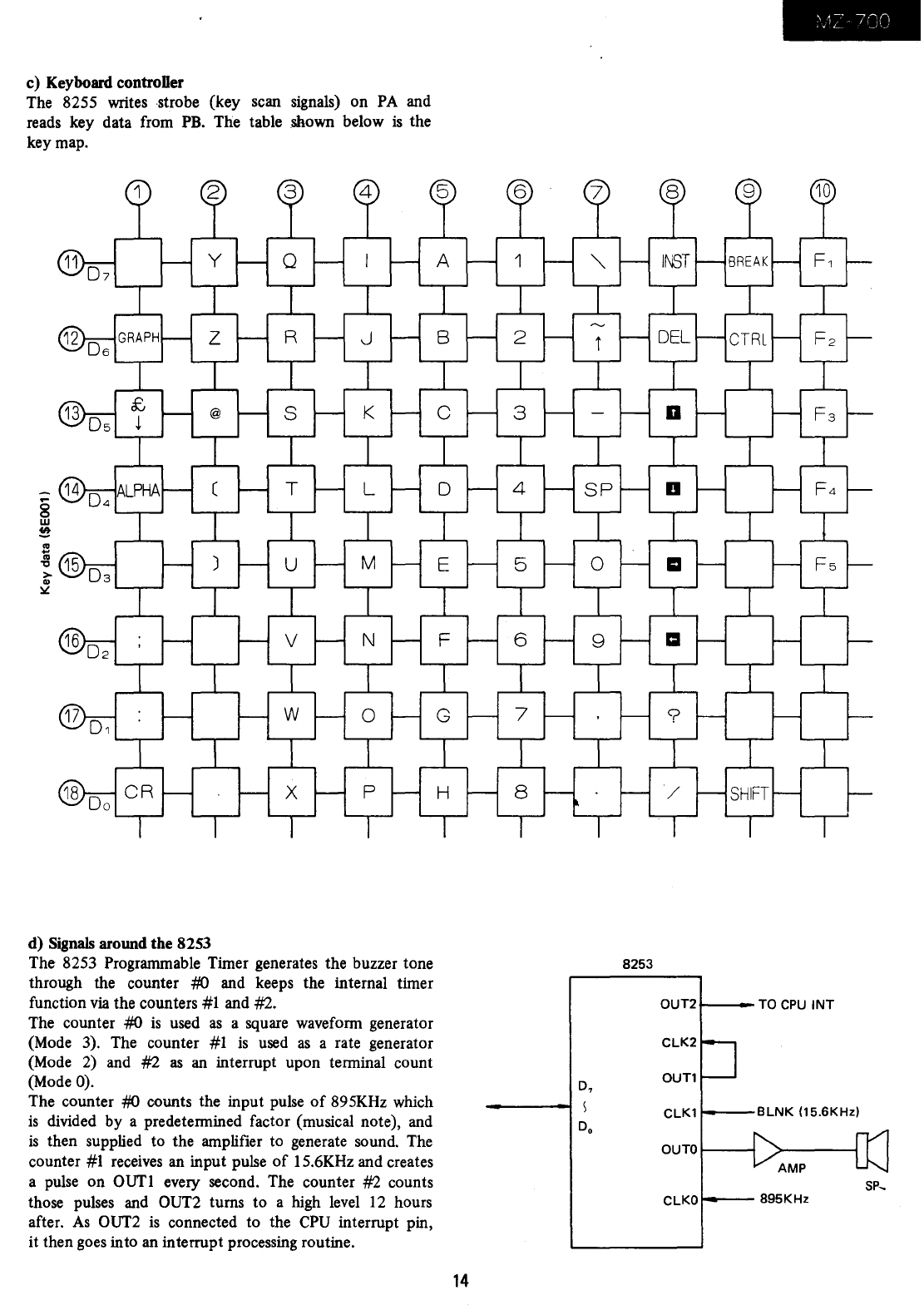
c) Keyboard controDer
The 8255 writes strobe (key scan signals) on
PA
and
reads key data from
PB.
The table shown below
is
the
key map.
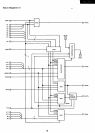
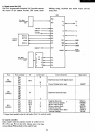
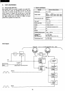
d) Signals around the 8253
The 8253 Programmable Timer generates the buzzer tone
through the counter
#(J and keeps the internal timer
function
via
the counters
#1
and #2.
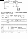
The counter #(J
is
used
as
a square waveform generator
(Mode 3). The counter #1
is
used
as
a rate generator
(Mode
2)
and #2
as
an
interrupt upon terminal count
(Mode
0).
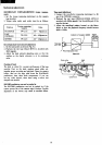
The counter #(J counts the input pulse
of
895KHz which
is
divided by a predetermined factor (musical note), and
is
then supplied to the amplifier to generate sound. The
counter
#1
receives
an input pulse
of
15.6KHz and creates
a
pulse
on OUTl every second. The counter #2 counts
those pulses
and
OUT2 turns to a high
level
12
hours
after.
As
OUT2
is
connected to the
CPU
interrupt pin,
it then goes into an interrupt processing routine.
8253
D7
Do
14
OUT2+----TO
CPU
INT
OUT1
ClK1
BlNK
05.6KHz)
OUTO
sp,
ClKO
895KHz