


E-79
Appendix
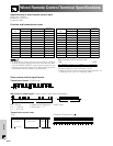
Connecting Pin Assignments
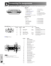
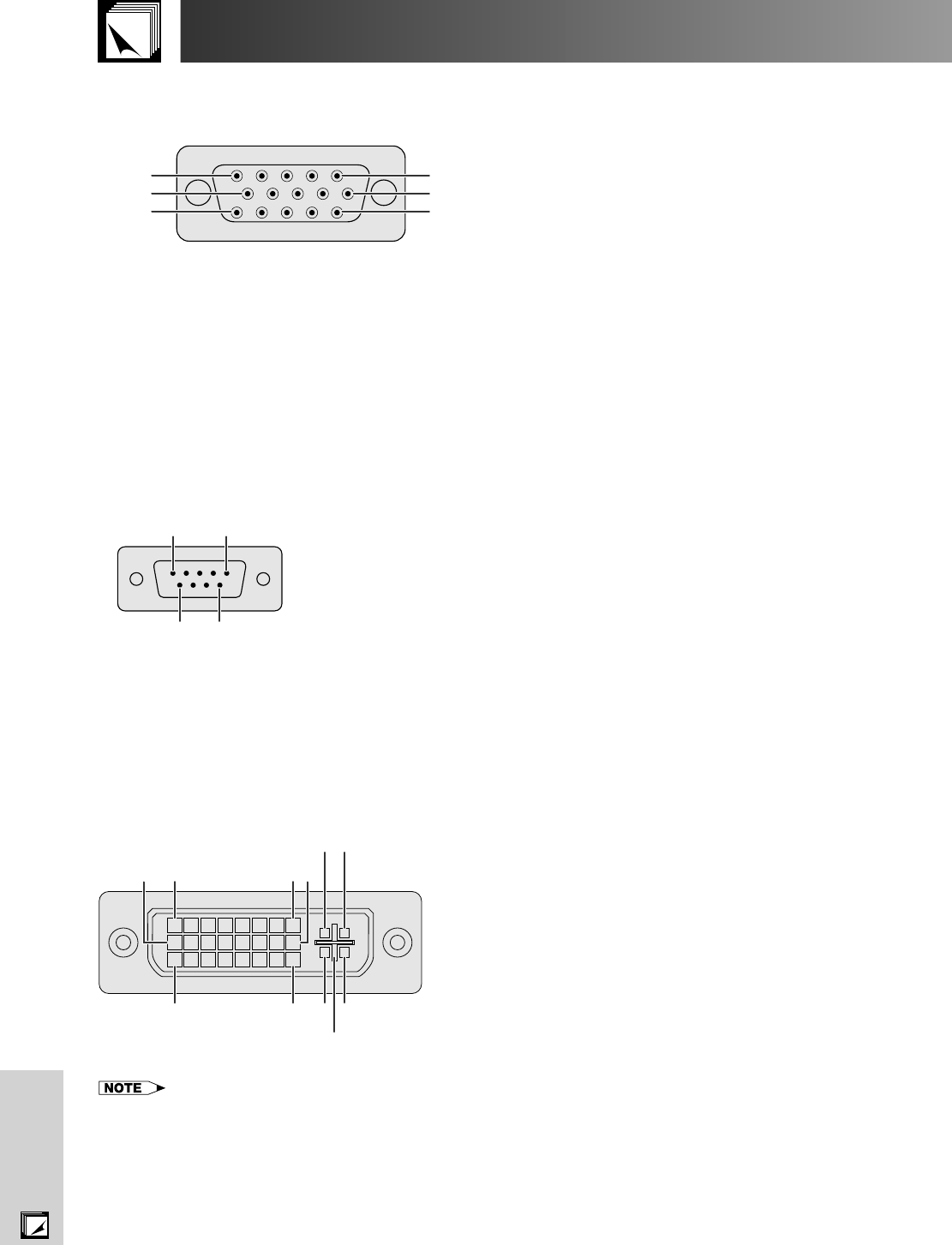
INPUT 1 RGB and OUTPUT (INPUT 1, 2) Signal Input Ports: 15-pin Mini D-sub female connector
RGB Input
Analog
1. Video input (red)
2. Video input
(green/sync on green)
3. Video input (blue)
4. Reserve input 1
5. Composite sync
6. Earth (red)
7. Earth (green/sync on green)
8. Earth (blue)
9. Not connected
10. GND
11. GND
12. Bi-directional data
13. Horizontal sync signal
14. Vertical sync signal
15. Data clock
RS-232C Port: 9-pin D-sub male connector of the DIN-D-sub RS-232C cable
5
10
15
1
6
11
Pin No. Signal Name I/O Reference
1 CD Not connected
2 RD Receive Data Input Connected to internal circuit
3 SD Send Data Output Connected to internal circuit
4 ER Not connected
5 SG Signal Ground Connected to internal circuit
6 DR Data Set Ready Output Not connected
7 RS Request to Send Output Connected to internal circuit
8 CS Clear to Send Input Connected to internal circuit
9 CI Not connected
15
69
DVI Port: 29-pin
91 816
C1C2
C32417 C4
C5
Pin No. Name
1 T.M.D.S. Data 2
2 T.M.D.S. Data 2ם
3 T.M.D.S. Data 2/4 Shield
4 T.M.D.S. Data 4*
3
5 T.M.D.S. Data 4ם*
3
6 DDC Clock
7 DDC Data
8 Analog Vertical Sync
9 T.M.D.S. Data 1
10 T.M.D.S. Data 1ם
11 T.M.D.S. Data 1/3 Shield
12 T.M.D.S. Data 3*
3
13 T.M.D.S. Data 3ם*
3
14 ם5 V Power
15 Ground*
1
16 Hot Plug Detect
17 T.M.D.S. Data 0
18 T.M.D.S. Data 0
19 T.M.D.S. Data 0/5 Shield
20 T.M.D.S. Data 5*
3
21 T.M.D.S. Data 5ם*
3
22 T.M.D.S. Clock Shield
23 T.M.D.S. Clockם
24 T.M.D.S. Clock
C1 Analog Red
C2 Analog Green
C3 Analog Blue
C4 Analog Horizontal sync
C5 Analog Ground*
2
• *
1
Return for ם5 V, Hsync. and Vsync.
• *
2
Analog R, G and B return
• *
3
These pins are not used on this equipment.
Component Input
Analog
1. P
R (CR)
2. Y
3. P
B (CB)
4. Not connected
5. Not connected
6. Earth (P
R)
7. Earth (Y)
8. Earth (P
B)
9. Not connected
10. Not connected
11. Not connected
12. Not connected
13. Not connected
14. Not connected
15. Not connected