


Chapter 5 Control From Editing
Control Units
Chapter 5 Control From Editing Control Units 5-9
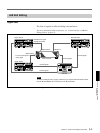
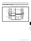
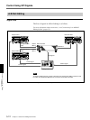
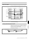
Downstream key control using GPI signals
You can use signals from the GPI output connector on the BVE-900/910/
2000 to turn the DFS-700/700P downstream key function on and off. Input
the GPI signals to the T2 connector on the rear panel of the DFS-700/
700P. (The BVE-2000 can also use 9-pin serial control signals to turn the
downstream key on and off and to set the transition duration.)
Preparations
Make the following preparations to control the DFS-700/700P from the
BVE-900/2000-series editor.
For details about operation, refer to the Operating Instructions or User’s Guide
supplied with the editor.
On the DFS-700/700P
• In page 1 of the setup menu, set F3(PORTS) to “PVE-500”.
• To accept 9-pin serial control signals, press the EDITOR button on the
control panel, turning it on. To accept GPI signals, press the GPI button,
turning it on.
(When the DFS-700/700P is powered on, it accepts either 9-pin serial
control signals or GPI signals.)
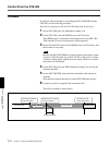
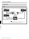
• To improve editing accuracy, supply a reference sync signal to the VCRs
and editing control unit from the BLACK BURST OUT connectors on
the DFS-700/700P.
On the recorder VCR
Set the recorder VCR so that it enters PB (playback) mode when stopped.
(If the VCR has a selector for PB or PB/EE, set it to PB.)
On the BVE-900/910
Set the PVW (preview) mode to EE.
• BVE-900 with no BKE-900K installed: In SYSTEM SETUP mode, set
BYTE-1 of the MAIN BLOCK INTERFACE parameters to hexadecimal
“01” (EE).
• BVE-910, or BVE-900 with BKE-900K installed: In SYSTEM SETUP
mode, set PVW MODE under SW’ER CONFIGURATION to EE.
On the BVE-2000
• In SYSTEM SETUP mode, set PVW MODE under SW’ER
CONFIGURATION to EE.
• In SYSTEM SETUP mode, set SW’ER TYPE under SW’ER
CONFIGURATION to DFS.
However, for versions 2.24 and later of the BVE-2000, select DFS-700/
700P.