


Chapter 2 Location and Function of
Parts and Controls
Chapter 2 Location and Function of Parts and Controls 2-15
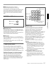
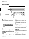
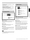
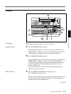
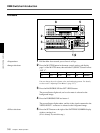
7 CLEAN OUT connector (BNC-type)
Outputs serial digital signals (270 MHz). Using the
setup menu, you can select the output from the
following three signals.
CLEAN OUT: The program output signal, without
the downstream key inserted.
PVW OUT: The signal output is the same as the
program output after completion of the effect
transition. The title area can also be shown.
KEY OUT: This outputs a key signal corresponding
to the shape of a selected effect. Use it as the key
source input to another device.
8 PVW (preview) connector (BNC-type)
This is an analog composite preview output. The signal
output is the same as the program output after
completion of the effect transition. It is not possible to
include the title area.
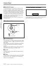
9 BLACK BURST OUT 1 to 3 connectors (BNC-
type)
These output the black burst signals generated by the
synchronizing signal generator internal to this unit.
When an external synchronizing signal is input to the
REF. VIDEO IN connectors, the black burst signal
output is locked to the external synchronizing signal.
Use the output from these connectors as a reference
synchronizing signal when synchronizing input signal
sources (character generators, etc.), or when
synchronizing this unit with a VTR or editor to
improve the precision of editing.
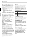
q; DSK (downstream keyer) KEY IN connectors
(BNC-type) and 75 Ω terminator switch
Input the key source signal for a downstream key,
from a character generator or other device.
When the 75 Ω terminator switch is in the OFF
position, the connectors provide a loop-through
connection; with the key signal input to one connector,
the other provides the same key source signal to
another device. By connecting to an analog component
Y connector on this unit, you can use it as a title key
source.
When not using the loop-through output, the 75 Ω
terminatior switch must be in the ON position.
qa REF. (reference) VIDEO IN connectors (BNC-
type) and 75Ω terminator switch
When using this unit synchronized to an external
signal, input the external reference signal (black burst).
When the 75Ω terminatior switch is in the OFF
position, the connectors provide a loop-through
connection; with the reference signal input to one
connector, the other provides the same reference signal
for another device. When not using the loop-through
output, the 75Ω terminatior switch must be in the ON
position.
qs GPI/T (GPI/trigger) 1 and 2 connectors (BNC-
type)
Input external trigger signals. These are used when
controlling editing with GPI signals or an editor (BVE-
600).
qd U (ground) terminal
Connect this to ground as required.
qf - AC IN connector
With the supplied power cord, connect to the AC
supply.