


1 General Information
________________________________________________________________________________________________________________________________________________________________________________________________________________________
12 Product Manual Type: 637f 07-02-10-01-E-V0505.doc
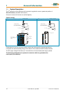
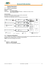
System Description
1.1.3 Compatibility with 637 Servo Drives (Not required for new projects)
The 637f series servo drives are essentially pin- and functionally compatible with the servo drives 637.
However, when a servo drive 637 is replaced with a 637f drive, the existing application must be checked and
carefully tested to determine compliance under the corresponding safety precautions.
The following points should be checked in any case and eventually be adjusted before the function test:
1. Motor direction parameter and limit switch setting (see release note V6.12)
2. Position setpoints and comparison values have to be quadrupled, resp. sixteenfold
(low encoder resolution at 637)
3. Coupling factors in synchronous applications have to be quadrupled, resp. sixteenfold
(low encoder resolution at 637)
4. Execution of BIAS- and PLC programs is 2.25 times quicker than with the 637. This can cause timing
problems with improper programming (e.g. wait times with NOPs)
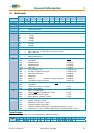
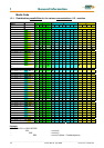
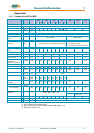
1.1.4 Compatibility with 637+ Servo Drives
(Not required for new projects)
Der Servoregler 637f ist voll funktionskompatibel zu 637+
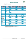
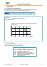
Funktion 637 637+ 637f
PC-Operating-Software
EASYRIDER
®
DOS Version
or Windows Version
EASYRIDER
®
Windows Version
EASYRIDER
®
Windows Version V8.xx
PC-Connection-Cable
see: chapter 2.6.2.3
PC - SUBD-9 to
LEMO connector (COM1)
PC - SUBD-9 to
4-pin module connector (COM1)
Power Part, Power Data and
Power Connectors
equal
Control Singals, Connector X10
see: chapter 2.3.2
equal pinning and function
Analog Set Point X10.5/18,
Resolution
12 bits
14 bits
Resolver Signals, Connector X30
see: chapter 2.4.2
pin–compatible
12/14 Bit Resolution
extended functionality
16 Bit Resolution
HIPERFACE
Feedback – Interface - Module
X300
see: chapter 2.4.1
-
- SIN / COS
Multifunction, Connector X40
see: chapter 2.5
compatible
extended functionality
Interface, Connector COM2
see: chapter 2.6.2 – 2.6.2.9
equal
extended functionality
CAN BUS 2, RP_2Cx
Options Module
see: chapter 2.6.2 – 2.6.2.10
equal
extended functionality
RP_SBT
Operating Modes, BIAS –
Functions
see: chapter 3 and 13.2
command set compatible
position value
12/14 bits ≈ 1revolution
future extensions possible
position value 16 bit ≈ 1 revolution
PROG-Key present
not available
Analog-Output - Test Signals
MP1/MP2:
> connector X 10
X 10.6 / X 10.17
> Front Test Sockets yes no
Technical Data
Analog Out
MP1 / X10.17
MP2 / X10.6
7 bits , Rout = 10 kOhm
7 bits , Rout = 10 kOhm
8 bits , Rout = 1.8 kOhm
10 bits , Rout = 1.8 kOhm
Control Loops
see: chapter 11.5
performance boost
compared
to 637:
cycle time twice as fast
performance boost
as
compared to 637f:
cycle time for speed twice as
fast,
position eight times as fast
Control Loop Parameters
Generally compatible,
possible optimization required
Jumper
see: chapter 7.1
JP2.2, JP2.3, JP2.7, JP2.8