


Wiring Instructions 6
________________________________________________________________________________________________________________________________________________________________________________________________________________________
07-02-10-01-E-V0505.doc Product Manaul Type: 637f 57
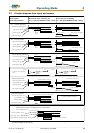
6 Wiring instructions
6.1 General Information
Digital servo drives are designed for operation in metallic grounded enclosures.
For perfect operation as well as for observance of all regulations the front board must be connected
with the enclosure electrically and fixed.
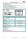
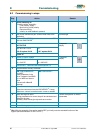
6.2 Control cabling
Recommended cross section 0,25 mm².The control signal lines must be laid seperate from the power
signal lines.(see chapter 6.7.1)
The resolver cable must contain three shielded pairs and must be shielded as a whole. The shielding
should be connected to the ground spread out on the regulator side. We recommend using SSD Drives
resolver cable KIR. Cable for transmitting data are always to be laid shielded !
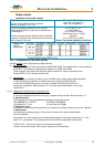
6.3 Power cabling
Recommended section according to rated current. Use only 75° Cu-cables.
6.4 Installation of the rack
When the rack is secured not in a hinged bay but on a mounting plate, it is recommended to do the wiring
of the connections for the power connector X50 on the rear of the rack before installing. With hinged-bay
installation, the customer must ensure that the parts sensitive to voltage such as the Ucc bus, mains
supply lines, etc., are protected against electric shock.
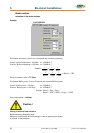
6.5 Analog setpoint
The setpoint input is a differential input. Therefore the poling can be done depending on the requirements.
Important: the setpoint voltage must be galvanically connected to the reference potential of the control
connections (plug X10). It is possible to connect one pole directly to GND.
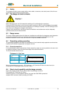
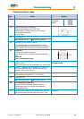
6.6 Safety rules
Caution !
Plug / unplug all modules only when
Ucc (DC-BUS) is off, that is, the green LED on the power supply module is off and the discharge
time > 3 minutes has elapsed.
The user must ensure protection against accidental touching.
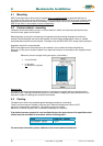
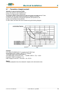
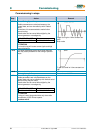
6.7 Electromagnetic compatibility (EMC)
Confirmity in accordance with the EEC Directive 89/336/EEC has been evaluated using a reference-
system, consisting of a compact type drive and a line-filter on mounting-plate,
connected to an AC-syncronous motor.
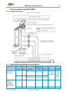
Mainly responsible for EMC-emissions is the motor cable. So this has to be installed exeptional carefully.
The layout of grounding is very important. Grounding has to be low-impedant for high frequences. That
means, all ground-connecting parts have to use area.
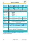
The measurements made are valid under the use of SSD Drives - cables, suppression aids and line filters
and by application of the following wiring instructions: