


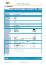

Table of Contents
________________________________________________________________________________________________________________________________________________________________________________________________________________________
4 Product Manual Type: 637f 07-02-10-01-E-V0505.doc
Seite
The Most Important Thing First ........................................................................7
Safety Precation .................................................................................................8
1 General Information................................................................................ 10
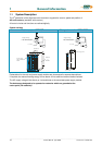
1.1 System Description.......................................................................................................................10
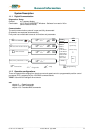
1.1.1 Digital Communication..................................................................................................................11
1.1.2 Operation configurations...............................................................................................................11
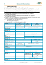
1.1.3 Compatibility with 637 Servo Drives (Not required for new projects)...........................................12
1.1.4 Compatibility with 637+ Servo Drives..........................................................................................12
1.2 Type Code ...............................................................................Fehler! Textmarke nicht definiert.
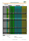
1.2.1 Combination possibilities for the various communications / I/O - modules ..................................14
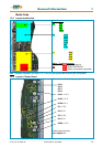
1.2.2 Layout module slots......................................................................................................................15
1.2.3 Layout of Power Board .................................................................................................................15
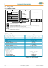
1.3 Range Data...................................................................................................................................16
1.3.1 Insulation Concept........................................................................................................................16
1.3.2 General Data.................................................................................................................................16
1.3.3 Compact Units 637f/K D6R...........................................................................................................17
1.3.4 Plug-In Modules 637f/D6R............................................................................................................18
1.3.5 Single- and Three-Phase Supply..................................................................................................19
1.3.6 Output Power................................................................................................................................20
1.4 Dimensions ...................................................................................................................................21
1.4.1 Dimensions for Compact Device and Plug-In Module..................................................................21
1.4.2 EMC-Clip (optional) .....................................................................................................................22
2 Connector Assignments and Functions ..............................................23
2.1 General View of Connections for Compact Device 637f/ K D6R 02 – 10 ....................................23
2.1.1 637f/K D6R 02...10 Width 14 HP..................................................................................................23
2.1.2 637f/K D6R 16...30 Width 20 HP..................................................................................................24
2.2 Connector Pin Assignments and Contact Functions....................................................................25
2.2.1 Power Connections for Plug-In Module 637f/D6R........................................................................25
2.3 Signal Connections.......................................................................................................................26
2.3.1 Control Signal Plug X10 - SUB D25 Socket .................................................................................26
2.4 Feedback Sensor X30 ..................................................................................................................29
2.4.1 Function module X300..................................................................................................................29
2.4.2 Feedback Sensor Connection X30 (SUB D 09 Socket) ...............................................................30
2.5 Multi-function X40 .........................................................................................................................31
2.5.1 Incremental Output .......................................................................................................................32
2.5.2 Incremental-Input..........................................................................................................................32
2.5.3 Stepper Motor Input......................................................................................................................33
2.5.4 Stepper Motor Input......................................................................................................................33
2.5.5 SSI Encoder Interface...................................................................................................................34
2.6 Digital Interfaces ...........................................................................................................................35
2.6.1 Service Interface - COM1 (RS232)...............................................................................................35
2.6.2 Fieldbus Interface - COM2............................................................................................................36
2.7 Option module RP SBT ................................................................................................................44
2.7.1 Safe Stop ......................................................................................................................................44
2.7.2 Brake control and PTC evaluation................................................................................................45