


5 Electrical Installation
________________________________________________________________________________________________________________________________________________________________________________________________________________________
54 Product Manual Type: 637f 07-02-10-01-E-V0505.doc
5.8 Brake resistor
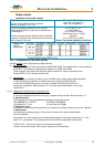
5.8.1 Selection of the brake resistor
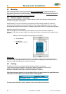
The energy of a moving system flows back to the Drive. The DC-Bus capacitors are able to take a small
value. The rest has to be converted to heat by a resistor.
Switching of this brake resistor depends on the DC-Bus voltage.
The load of the resistor is simulated and supervised electronically
(EASYRIDER
®
Windows - Software). Peak power (Pmax) and continuous power (Pd) ratings have to be
sufficient to meet the requirements of the application.
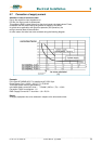
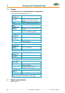
n1
RPM
T
tb1
t [sec]
Movement
I [A]
Ib
t [sec]
Braking-Current
Values for Example
n1 = 3000 RPM
tb1 = 0,1 sec.
T = 2,0 sec.
J = 0,0005 kgm² Total Inertia
Definition of Data
RL = 0,3 Oh m
Speed at Brake-Start
Braking Time
Cyc le-Time
Cable-Resistance
Braking-Current Ib = 3,2 A
Motor-Resistance
Rph = 3,6 Ohm
Calculation
Step 1
Calculation of brake-power
(Approximation. Capacitor-load, friction-and drive-
losses neglected)
example
Power of motion:
Pkin = 0,0055 * J * n1² / tb1 [W]
Pkin = 0,0055 * 0,0005 * 3000²/0,1
Pkin = 247 W
Motor-losses:
Pvmot = Ib² * (Ri + RL) [W]
Pvmot = 3,2² * (3,6 + 0,3)
Pvmot = 40 W
Cont. Power:
Pd = 0,9 * (Pkin-Pvmot) * tb1 / T
[W]
Pd = 0,9 * (247 - 40) * 0,1 / 2
Pd = 9,3 W
Peak-Power:
Pmax = (1,8 * Pkin) - Pvmot [W]
Pmax = (1,8 * 247) - 40
Pmax = 405 W
used units:
J total inertia [kgm²]
n1 speed at Brake-Start [RPM]
tb1 braking time [Sec]
T cykle time [Sec]
Ib brake-current [A]
Rph resistance of motor (between terminals) [Ω]
RL line resistance of motor cable [Ω]