


Electrical Installation 5
________________________________________________________________________________________________________________________________________________________________________________________________________________________
07-02-10-01-E-V0505.doc Product Manaul Type: 637f 55
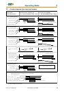
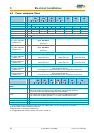
Brake resistor
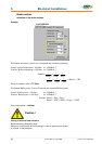
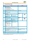
selection of the brake resistor
Step 2
Internal / external Brake-resistor required ?
see data in chapter 1.3.3 / 1.3.4
Example-Drive type
637f/K D6R04-7
In case of unsufficient capability or not included
internal Brake-Resistor, a type may be selected from
the following list
External and internal Brake-Resistors will be switched
in parallel. The internal and external performance-Data
may be added in this case.
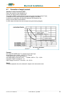
acc. to data in 1.3.3:
internal resistor:
Cont. Power Pd = 30W
Peak Power Pmax = 1700W
Required:
Pd = 9,3W Pmax = 405W
Result: The internal capability is sufficient
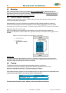
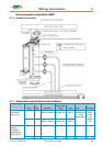
5.8.2 Configuration of the brake resistor
Possible ballast circuit configurations at digital devices
a) Compact design
The plug-in modules of servo-control series 635/637/637+/637f are provided with an on board ballast
electronics. It is intended for application as compact unit KDER resp. KD6R.
These compact units contain the necessary ballast resistor incl. fuse for the ballast circuit.
Except KD6R 16..30-7 (external resistor only).
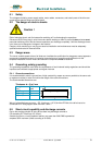
b) Rack design
While the plug-in modules are used in a rack, the NEB power supply module takes dissipation
of the braking energy (adjustment of ballast monitoring: please see NEB manual).
In this case the ballast electronics of the plug-in module will be deactivated with the
configuration parameter "Ballast activate = N". All further ballast parameters are no longer
relevant then.
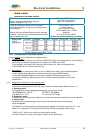
r.g. a) Adjustment of ballast circuit for compact units:
1. Ballast electronics activated:
In this case the ballast electronics of the plug-in module will be activated. "Ballast activate = J".
2. Operating point:
The operating point has to be adjusted dependent on the voltage variant.
"Ucc Ballast on = 375 V" for 230 V AC supply
"Ucc Ballast on = 720 V" for 400..460 V AC supply
3. Resistance value:
As resistance value, the parallel resistance from internal and external resistance has to be adjusted.
4. Rated power:
As ballast power (braking energy), the sum total of internal and external resistor power
has to be adjusted.
Precondition for correct monitoring of shunted ballast resistors is the nearly same ratio of P - cont.
power to P - pulse power. This is guarantied with the SSD Drives standard combinations.
..KD6R 16..30-7 units do not contain an internal ballast resistor.
At these versions the values of the external resistor can be feed directly.