


2 Connector Assignments and Functions
________________________________________________________________________________________________________________________________________________________________________________________________________________________
44 Product Manual Type: 637f 07-02-10-01-E-V0505.doc
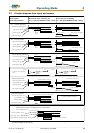
2.7 Option module RP SBT
2.7.1 Safe Stop
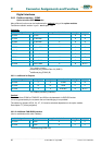
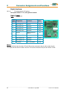
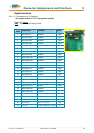
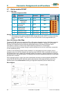
Connector assignment X290:
PIN
X290
designation comment status
1 Input Active
1)
OPTO Input
2 Reference point
Input Active
OPTO Input
3 Starting lockout
deactivated
Relais Input
4 Reference point
Starting lockout
Relais Input
5 Checkback contact Free contact Break contact
6 Checkback contact Free contact Break contact
Hinweis:
1)
With employment the option module RP SBT changes the function “AKTIV” from the connecting
plug X10.22 after X290.1! The input X10.22 can be used then as free programmable input
(BIAS).
Use of the function Safe Stop
The option RP_SBT of the drive controller 637fxx-x.S5 supports the safety function “Safe Stop”, protection
against unexpected starting, according to the requirements of the EN954-1 “Category 3” and EN1037.
The stop of the machine must be caused and guaranteed before by the external machine control.
This applies in particular to vertical axes without selflocking mechanics or counterweight.
If an error arises in the drive system during the active brake phase, the axis can coast down uncontrolled
or even accelerate actively.
In order to use the Starting lockout function intended, it is to be looped into the net contactor circle or
emergency stop circle with the obligation-led reporting contact X290.5/6. With not plausible functioning of
the Starting lockout relay, related to the operating mode of the machine, a galvanic separation of the drive
concerned from the net must take place. The Starting lockout and the associated mode may be used again
only after error correction.
Due to a danger analysis / view of risk (to be accomplished according to machine guideline 89/392/EWG
and/or EN 292; EN 954 and EN 1050) the machine manufacturer must project the safety circuit of its
machine types for the entire machine including all integrated components (also the electric drives).
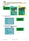
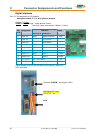
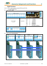
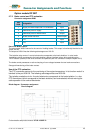
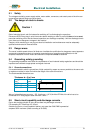
Block diagram: