


121
n g-pin graphics mode
In the early part of this chapter, we said that the bottom pin of
the print head is not normally used in the graphics modes.
That’s because most computers communicate with parallel-type
peripheral devices using eight data lines. When the peripheral is
a printer, each data line corresponds to one pin on the print
head. Thus each byte sent will fire up to eight pins.
But the printer has 9 pins available. So how do you fire the
ninth pin with only 8 data lines? In fact, do you really want to
bother with just one extra pin? Well, for such graphics-intensive
applications as screen dumps, printing 9 pins at a time can
speed up the process considerably. For this purpose, your
printer has a special g-pin graphics mode (it won’t, however,
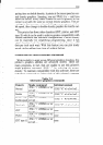
work with 7-bit interface systems). In this mode the printer
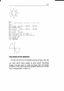
takes 2 bytes to fire all 9 pins as shown in Figure 7-3.
128
64
32
16
First byte
8
4
2
1
128
Second byte
(only the top bit is used)
Figure 7-3. Your printer takes 2 bytes to fire all 9 pins in case of
the g-pin graphics mode.
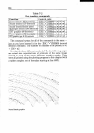
In addition, you can select the print density by the value of nO.
When nU is 0 the normal density is selected, and when nO is 1
the double density is selected.
Since computers are faster than printers, there is no signifi-
cant time loss in printing a single line of graphics with 9 pins.
You get 9 dots per line in about the same time as you get 8 dots
in the other graphics modes.