


LTO Configurations
332 SL500 User’s Guide • July 2008 Revision: KA • 96116
LTO Configurations
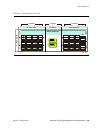
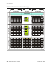
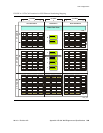
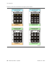
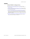
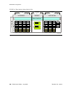
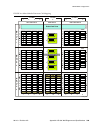
The following figures show LTO storage cell and tape drive locations.
■ FIGURE A-1, “Base Module LTO Cells” on page 333 shows a library with only a Base
Module.
■ FIGURE A-2, “LTO Cell Locations for Firmware Site Mapping” on page 334 shows a
library with a Base Module that has nine reserved cells, one Drive Expansion
Module, and one Cartridge Expansion Module.
■ FIGURE A-3, “LTO Cell Locations for SCSI Element Numbering Mapping” on
page 335 shows a library with a Base Module that has two reserved cells, one Drive
Expansion Module, and one Cartridge Expansion Module. The storage cell
numbering begins with the first cell after the reserved cells in column 1. The figure
shows two reserved cells, but there could be more. If the reserved cells are
configured as storage cells, the top cell (row 1) would be 1.
■ FIGURE A-4, “LTO Cells for Back Wall of Cartridge Expansion Module” on page 336
shows the cell capacity of a Cartridge Expansion Module according to which type of
module is installed above and below it.