


Controls and Indicators
10 SL500 User’s Guide • July 2008 Revision: KA • 96116
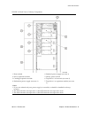
Controls and Indicators
Note – This section describes the controls and indicators that you can use to monitor
and troubleshoot the library. For tape drive controls and indicators, refer to the vendor
publications and Web sites. For details on the Local Operator Panel, see the SL500 Local
Operator Panel Guide, p/n 96258.
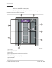
Power Switch
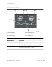
When the switch (see FIGURE 1-2) is in the On position (1) the library and tape drives
are powered-on. When the switch is in the Off position (0), the library and tape drives
are powered-off.
Note – Earlier built libraries had power supplies that had individual power switches.
Later libraries have one power switch that controls all power supplies in the rack.
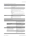
Power Supply LED
The following table describes the power supply LED.
Drive Tray LED
The following table describes the drive tray LED.
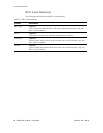
TABLE 1-3 Power Supply LED
Activity Meaning Action
On Power supply is active. Nothing, this is normal.
Off The power supply failed. The service representative might need
to replace the power supply.
The power supply is not receiving
power.
The service representative might need
to check the connections and voltages.
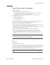
TABLE 1-4 Drive Tray LED
Activity Meaning Action
On solid The drive fan failed, the temperature is
too high.
The service representative might need
to replace the fan.