


126
Sundance Technology ST201 PRELIMINARY draft 2
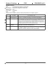
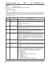
POWERMGMTCAP
Class....................PCI Configuration Registers, Power Management
Base Address ......PCI device configuration header start
Address Offset.....0x52
Access Mode.......Read Only
Width ...................16 bits
This register provides information about the adapter’s power management capabilities. The reset default is
7601h, but several bits are loaded from EEPROM shortly after reset.
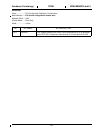
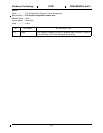
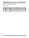
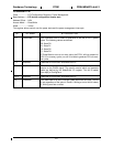
BIT BIT NAME BIT DESCRIPTION
2..0 Version This read-only field returns 1h, as specified in the PCI Bus Power Man-
agement Specification Revision 1.0.
8..3 Reserved Reserved for future use. Should be set to 0.
9 D1Support This read-only bit, when set, indicates that this device supports the D1
power state. This value of this bit is determined by bit 4 in the
EEPROM ConfigParm.
10 D2Support This read-only bit, when set, indicates that this device supports the D2
power state. This value of this bit is determined by bit 5 in the
EEPROM ConfigParm.
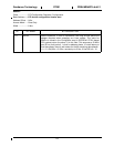
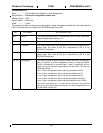
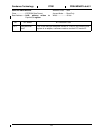
15..11 PmeSupport This read-only field indicates the power states from which this device is
able to generate a power management event by asserting PMEN.
Each bit corresponds to a power state. A zero in a particular bit indi-
cates that events cannot be generated from that state. The bits are
defined as follows:
xxxx1: Power management events can be generated from D0.
xxx1x: Power management events can be generated from D1.
xx1xx: Power management events can be generated from D2.
x1xxx: Power management events can be generated from D3hot.
1xxxx: Power management events can be generated from D3Cold.
The ST201 hard-wires bit 11 to zero and bit 14 to one. The values of
bits 12,13, and 15 are determined by bits 4, 5 and 3 respectively from
the EEPROM ConfigParm.